


2 Pelco Manual C429M-B (2/98)
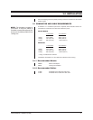
REVISION HISTORY
Manual # Date Comments
C429M-A 10/94 Wire colors revised on figures 2-4, 6 and 7. (Pin 8 -
Figure 2; Pins 8 & 23 - Figures 3 and 4; Pins 8, 11, 12,
13 - Figures 6 and 7.)
C429M-B 7/96 Revised to include new models SS22 and SS2002-SL.
8/96 Revised Section 5.0, Mechanical Parts List, regarding
lower dome part numbers and quantities of velcro.
7/97 Corrected wiring for pins 19 and 27 in Figure 7 per ECO
97-235.
2/98 Revised Section 6.0, Maintenance. Changed manual to
new style.
LIST OF ILLUSTRATIONS
Figure Page
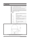
1 SS20/SS22/SS2000/SS2002 Dimension Drawing.............................4
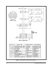
2 SS2000/SS2000-SL/SS2002-SL Wiring Diagram..............................6
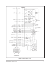
3 SS2000-PP Wiring Diagram ..............................................................7
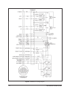
4 SS2000SL-PP Wiring Diagram .........................................................8
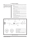
5 Connector Assembly ..........................................................................9
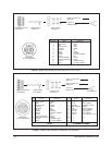
6 Mating Cable Assembly Configuration (non-PP Versions) ................10
7 Mating Cable Assembly Configuration (PP Versions) .......................10
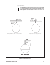
8 Mounting Configurations ...................................................................11
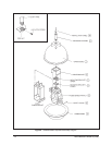
9 SS2000/SS2002 Exploded Assembly Diagram ................................14
10 Limit Stop Locations .........................................................................15
11 Tilt Limit Stop Modifications ..............................................................15
LIST OF TABLES
Table Page
A SS2000/SS2002 Exploded Assembly Diagram ................................13
CONTENTS
Section Page
1.0 GENERAL ..................................................................................................3
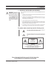
1.1 IMPORTANT SAFEGUARDS AND WARNINGS ...............................3
2.0 DESCRIPTION ..........................................................................................4
2.1 MODELS............................................................................................4
3.0 INSTALLATION ..........................................................................................5
3.1 CONDUCTOR AND CABLE REQUIREMENTS ................................5
3.1.1Recommended Mounts..............................................................5
3.1.2Recommended Cables ..............................................................5
3.2 CONNECTOR ASSEMBLY ................................................................9
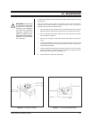
3.3 MOUNTING ......................................................................................11
3.4 DOME INSTALLATION .....................................................................12
4.0 EXPLODED ASSEMBLY DIAGRAM .........................................................13
5.0 ADJUSTMENTS .......................................................................................15
6.0 MAINTENANCE ........................................................................................16
7.0 SPECIFICATIONS ....................................................................................17
8.0 WARRANTY AND RETURN INFORMATION ...........................................20