


4/31
FV-L500B1
User’s Guide Rev. 1.01
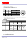
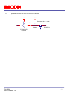
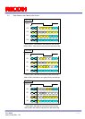
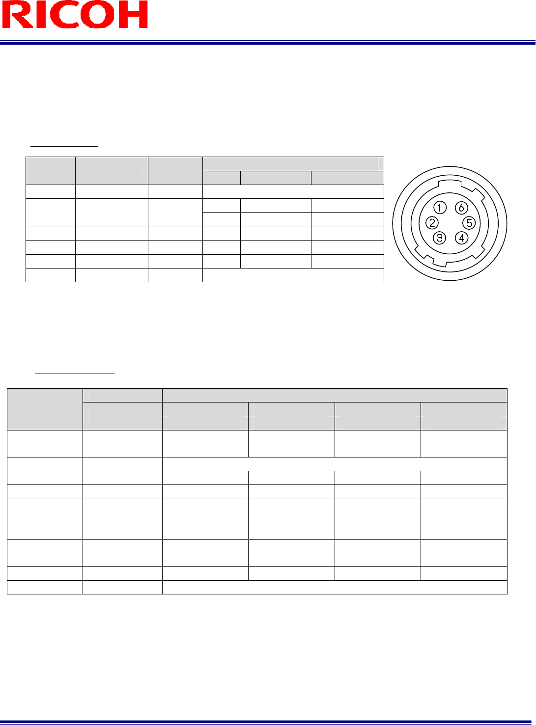
1.2 I/O Connector
HR10A-7R-6PB(Hirose)or equivalent
This connector is for input /output signals.
Use HR10A-7P-6S (Hirose) or equivalent for the cable side.
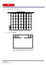
Pin Assignment
Input/output signals can be assigned through the camera setting communication (see table 4).
Trigger input signal can be assigned either on Camera Link connector (CC1) or on the No. 2 pin of the IO
connector through the camera setting communication.
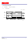
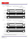
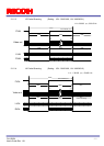
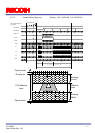
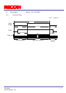
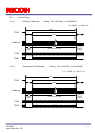
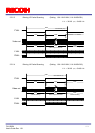
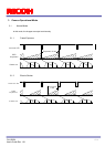
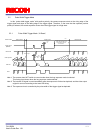
IO Signal Patterns
Note 1: Output trigger signal has a latency of 30CLK (Approximately 470 nseconds) from input trigger signal.
Note 2: To input trigger signal from the I/O connector, change the setting of 12H.5.
Note 3: EXPDUR becomes high during exposure.
Voltage
Pin No. Signal Name IN / OUT
Low Voltage High Voltage
1 GND IN 0V
IN 0 to +0.99V +2.3 to +3.3V
2 I/O-1 IN/OUT
OUT 0V +3.3V
3 I/O-2 OUT
OUT 0V +3.3V
4 I/O-3 OUT
OUT 0V +3.3V
5 I/O-4 OUT OUT 0V +3.3V
6 N.C.
Command No. HR10A-7R-6PB (Hirose)
No.2 Pin No.3 Pin No.4 Pin No.5 Pin
F0H[3..0]
I/O-1 (SP4) I/O-2 (SP3) I/O-3 (SP2) I/O-4 (SP1)
Option 0
(Initial Setting)
0H IN/TRG N/A N/A OUT/TRG
Option 1 1H For Test Use Only
Option 2 2H OUT/CC4 OUT/CC3 OUT/CC”2 OUT/CC1
Option 3 3H OUT/FVAL OUT/XSG OUT/XSUB OUT/CC1
Option 4 4H
OUT/FVAL OUT/LVAL
OUT/
Right Image Data
(MSB)
OUT/
Left Image Data
(MSB)
Option 5 5H OUT/XHD
(high-active)
OUT/EXPDUR
(Exposure)
OUT/TRG OUT/CC1
Option 6 6H OUT/VD N/A N/A OUT/HD
Others 7H-FH For Test Use Only