


Chapter 2. System Installation 7
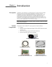
Connecting Your
CoolSNAP
Camera
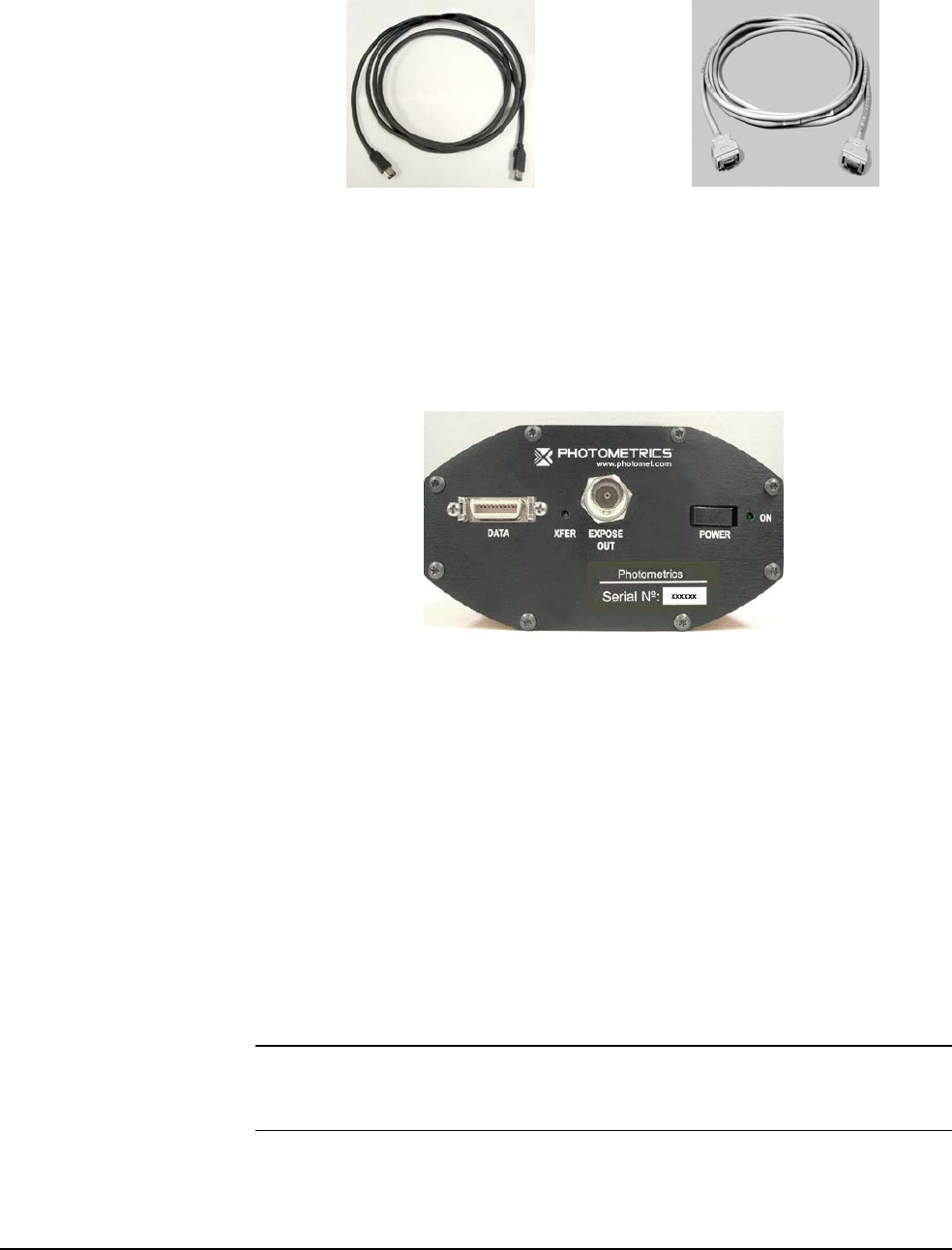
The CoolSNAP cable connects your CoolSNAP camera to the interface card. This
cable is designed to serve as a conduit both for data and power.
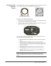
CoolSNAP IEEE-1394 Cable
CoolSNAP LVDS Cable
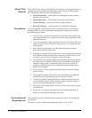
To connect your LVDS CoolSNAP camera:
1. Connect either end of the CoolSNAP LVDS cable to the CoolSNAP interface
card that you have installed in the host computer.
2. Connect the other end of the CoolSNAP LVDS cable to the DATA connector
located on the back of the camera (shown below).
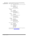
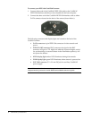
The following connectors and display lights, as well as the power switch, are
located on the back of the CoolSNAP camera.
• DATA connector: 20-pin, high-density connector for data transfer and
power.
• EXPOSE OUT connector: BNC connector; the signal at the BNC
connector will go to a TTL high level when the exposure begins; useful
for synchronizing an external shutter in the illumination pathway; will
not power the shutter.
• XFER display light: amber LED illuminates during data transfer.
• ON display light: green LED illuminates when camera is powered on.
• POWER switch: momentary on/off rocker switch (CoolSNAP
cf
) or
standard rocker switch (CoolSNAP
ES
).
Note: LVDS CoolSNAP cameras draw power from the PCI bus via the PCI card.
Therefore, the computer must be powered on for the LVDS CoolSNAP camera to
operate.