


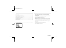
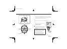
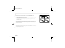
PARTS NAMES AND FUNCTIONS
6 Camera mounting screw hole (1/4"–20 UNC)
When mounting the camera to the mounting bracket, use this
installation hole.
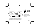
7 Lens cover fixing screw
8 GND (ground) terminal screw
Loosen the GND terminal screw, insert the coaxial cable into the
clamp and tighten the GND terminal screw.
9 VIDEO OUT terminal screw
Align the centre wire of the coaxial cable with the VIDEO OUT
terminal, then first tighten the cable clamp and then the VIDEO
OUT terminal screw.
• Cable type RG-6U (5C-2V)
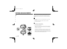
The view angle of this camera is as follows:
Horizontal: 71˚
Vertical: 53˚
Diagonal: 90˚
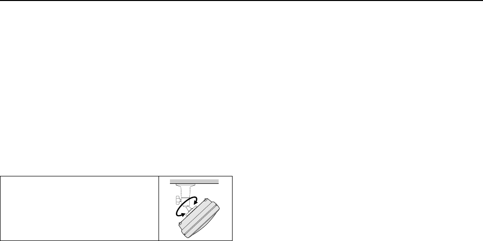
To adjust the camera angle, use the camera
mounting bracket (sold separately).
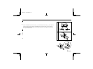
F Line phase volume
When using a camera switcher to connect 2 cameras or more to
one monitor, there may be a vertical roll of the images when
switched. In such a case, set as described below.
Switch the display on the monitor from camera 1 to camera 2.
Adjust the LINE PHASE volume on camera 2 until the vertical
roll of the image stops.
If more than two cameras are used, please repeat this procedure
for all the cameras.
CAUTION:
If the vertical roll cannot be corrected by setting the LINE PHASE
volume on camera 2, try setting the LINE PHASE volume on camera
1. If it still cannot be corrected, please check that the polarity of the
power cords of all connected devices is correct.
L73E4/US GB 1998, 20, 15
English 5