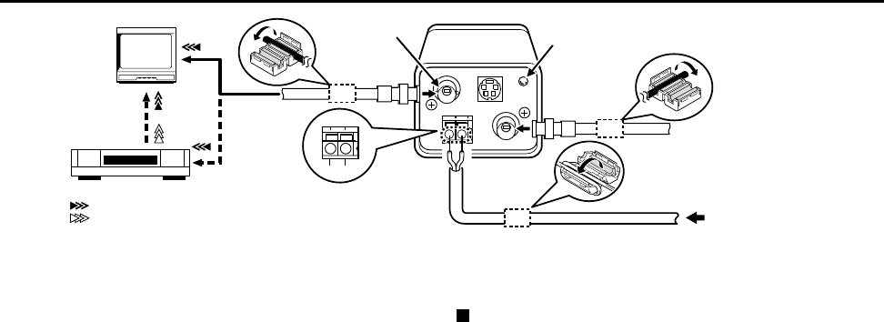
CONNECTIONS (VCC-6592P only)
Basic connection for monitoring or recording
The peripheral devices (VCR, monitor, lens, etc.) and cables are
sold separately.
1 Make the video signal connection between the camera and
the monitor or time lapse VCR.
2 Use a commercially available 12 V DC adaptor.
Connect an DC 12 V power source to the 12 V DC input terminal
on the back of the camera.
2A: When using this unit, the supplied clamping core (A or B) must be
installed on the power cord and BNC cable, in order to prevent
electromagnetic interference to the other devices connected.
3 Insert the plug of this power cord into a wall outlet.
The POWER indicator (A) will light. Adjust the picture on the
monitor using the Brightness and Contrast controls etc.
Coaxial cable type and maximum length
• Cable type RG-59U (3C-2V), 250 m maximum.
• Cable type RG-6U (5C-2V), 500 m maximum.
• Cable type RG-11U (7C-2V), 600 m maximum.
CAUTION:
• The RG-59U type cable should not be run through electrical
conduits or through the air.
• Using CCTV/Video-grade coaxial cable.
(Video signal connections)
: VIDEO IN
: VIDEO OUT
(A)
1
12 V DC input
12 V DC connection
Push to insert the cable
12 V DC
–
+
2A
2A
2
2A
3
(A)
(A)
(B)
L53H2, H4/XE GB 2001, 9, 18
English 9


