


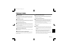
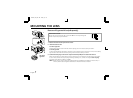
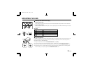
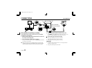
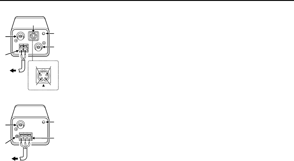
PARTS NAMES
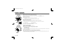
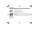
1 Video output connector (VIDEO OUT: BNC type)
Connect this connector to a device such as a VCR or monitor with a VIDEO IN connector.
2 Power input terminal
• VCC-6592P: 12 V DC input terminal (12 V DC, GND)
• VCC-6594P: 24 V AC input terminal (AC 24 V, AC 24 V, GND)
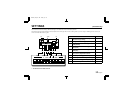
3 Y/C OUT connector (4 pin)
Separate Y (luminance) and C (chroma) signals are output from this terminal.
A better picture quality is obtained if the monitor or VCR is connected to this connector.
1 Y signal ground 2 C signal ground
3 Y signal: 1.0 Vp-p, 75 ohms, unbalanced, negative sync
4 C signal: 0.3 Vp-p, 75 ohms, unbalanced
4 Power indicator (POWER)
Comes on when the power to the camera is on.
5 External sync composite video signal input connector
(VBS IN: BNC type)
Connect to this connector the synchronizing signal output from a synchronizing signal device or the composite
signal of a video distributor.
6 Line phase adjustment volume (LINE PHASE) (VCC-6594P only)
When using two cameras or more, the image on the monitor may roll vertically when switching sources. This
rolling can be minimized by turning this volume.
1
4
2
5
3
1
2
4
3
1
4
6
2
(VCC-6594P)
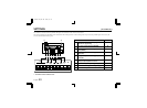
(VCC-6592P)
L53H2, H4/XE GB 2001, 9, 18
English 3