


5
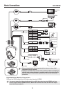
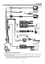
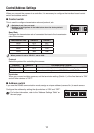
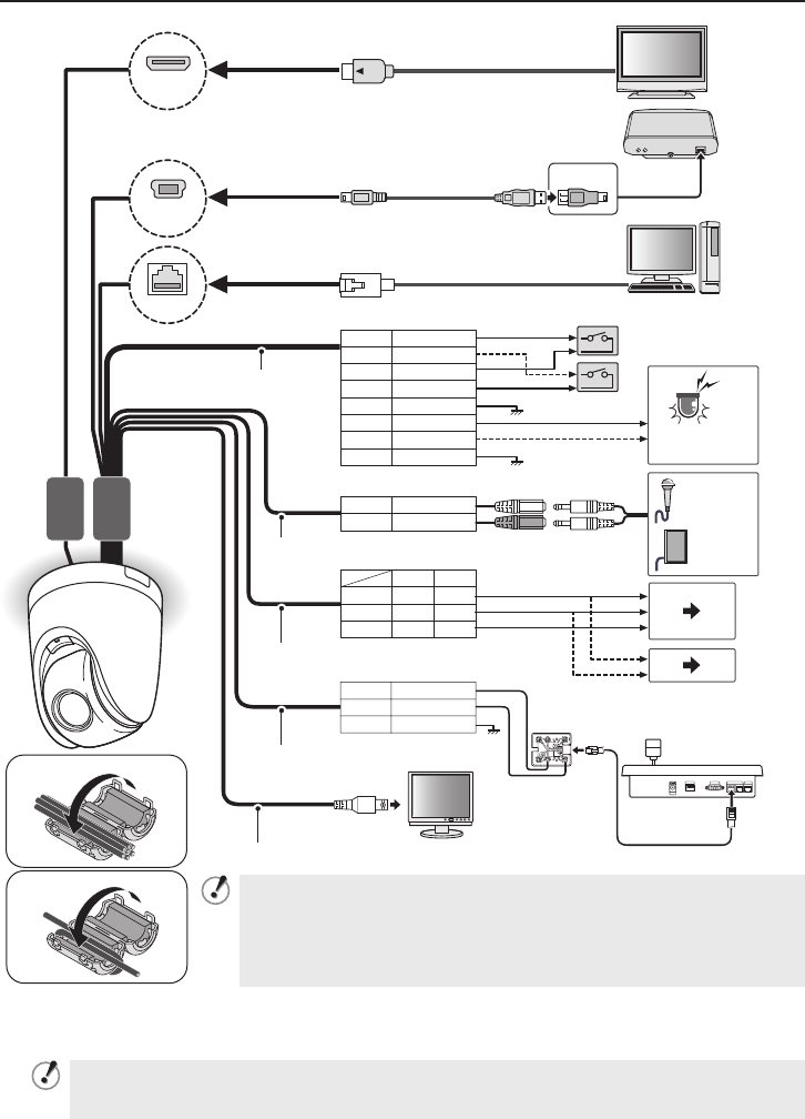
Basic Connections VCC-HD5400
+
-
~
~
DC12
GND
AC24
WHITE
WHITE
WHITE
AUDIO IN
RED
RED + ~
-
~
DC12
NC GND
GND
GND
AC24
ALARM_IN1
ORANGE
YELLOW
YELLOW
ALARM_OUT1
BROWN
ALARM_OUT2
GRAY
GRAY
ALARM_IN2
ALARM_IN3
ALARM_IN4
BLACK
BLACK
BLACK
BLACK
AUDIO OUT
WHITE
GND
RS485(B)
RS485(A)
*1
*2
USB
LAN
HDMI
Alarm cable
Audio cable
Power cable
Control cable
Video cable
Monitor
System controller
PC
HDD
High-definition
monitor
External
peripheral device
*3
*2 *1
Microphone
Speaker
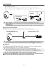
Before attempting the following connections, be sure to turn off all
components of your system.
Improper connection may cause smoke or failures. Before attempting to
connect each system component, carefully read the instruction manual
that comes with it to familiarize yourself with the correct connection
procedure.
•
•
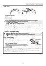
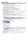
High-Definition Monitor Connection
Connect the HDMI cable to the HD video output terminal (HDMI).
You cannot output the video simultaneously from HD video output terminal (HDMI) and from
monitor output terminal (MONITOR OUT). When both terminals are used, the HD video output
terminal takes precedence.