


− 4 −
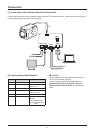
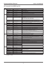
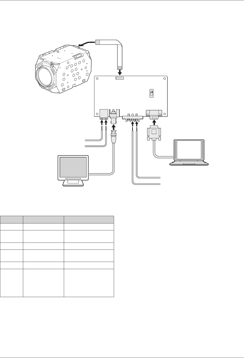
[1] Connection of the Interface Board and Camera Unit
Connect the camera unit and the interface board using the FFC (flexible flat cable). Connect the various terminals
of the interface board using the necessary cables.
DC12V
GND
V PULSE
GND
CN001
S0001
FFC
B
A
CN002
CN003CN004
CN005
Connection
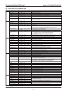
[2] Interface Board Specifications
Connector
Terminal Name Details
CN001 RS232C PC
CN002 Screw Power Source
(DC12V
±
1V)
CN003 BNC VIDEO OUTPUT
CN004 Push Lock V PULSE
(External Tuning)
CN005 FC Connector Camera Unit Connection
S0001
Slide Switch
RS-232C Cable Type
Selection
A Side: Straight Cable
B Side: Cross (Interlink)
Cable
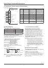
■
V PULSE
Input the signal of the following external tuning into
the V PULSE terminal (CN004).
Input a signal that satisfies the requirements in
[3] External Synchronous Signals 1 External
Synchronization Specifications on the following
page.