


18
Section 4 - REPAIR & ADJUSTMENTS
WARNING
DO NOT attempt any maintenance, adjustments or
service with engine and blade running. STOP engine
and blade. Disconnect spark plug wire and secure
away from spark plug. Engine and components are
HOT. Avoid serious burns, allow sufficient time for
all components to cool.
4.3.4. Replacing Rubber Driven Disc
(Continued from previous page)
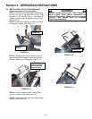
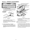
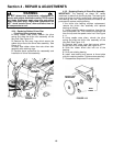
2. Using needle nose pliers, unhook the drive
spring and slide the driven disc assembly off the
hex shaft. See Figure 4.12.
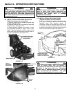
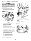
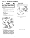
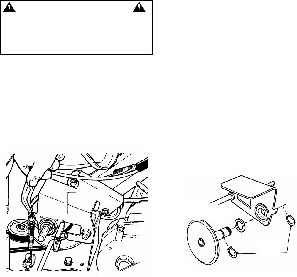
3. Remove the two snap rings which secure the
rubber driven disc to the driven disc assembly. See
Figure 4.13.
4. Install new rubber driven disc onto driven disc
assembly with retaining rings.
5. Reverse above procedures for reassembly and
installation of driven disc assembly.
FIGURE 4.12
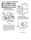
4.3.5. Replacing Bearing In Driven Disc Assembly
IMPORTANT: The bearing, on these “M” series
machines, is staked into the thrust plate. The bearing will
have to be driven out with a mallet and a large punch. A
new bearing with four retaining screws will have to be
purchased to replace existing bearing.
If the driven disc bearing requires replacement,
remove the driven disc assembly and replace
bearing as follows:
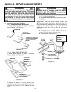
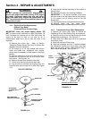
1. Using a small flat blade screwdriver, free the clip
from the transfer rod. Then remove the transfer rod
from the clip and the speed control rod. See Figure
4.11.
2. Using needle nose pliers, unhook the drive
spring and slide the driven disc assembly off the
hex shaft. See Figure 4.12.
3. Remove both snap rings that secure rubber
driven disc hub to thrust plate. See Figure 4.13.
4. Slide the rubber driven disc hub out of the
bearing.
5. Drive out existing bearing.
6. Install new bearing and secure to thrust plate
with four retaining screws. Tighten screws securely.
7. Reassemble components in reverse order.
FIGURE 4.13
DRIVE DISC
ASSEMBLY
INSTALL NEW
DRIVEN DISC
SNAP
RINGS