


20
Section 4 - REPAIR & ADJUSTMENTS
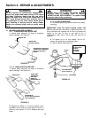
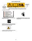
WARNING
DO NOT attempt any maintenance, adjustments or
service with engine and blade running. STOP engine
and blade. Disconnect spark plug wire and secure
away from spark plug. Engine and components are
HOT. Avoid serious burns, allow sufficient time for all
components to cool.
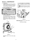
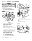
4.4.1. Engine Drive Belt Replacement
(Stretch Type Belts)
(Continued From Previous Page)
IMPORTANT: Drain fuel before tipping mower. DO
NOT tip machine with carburetor or spark plug down. Oil
from crankcase will saturate the air filter and cause the
engine to be hard to start or not start at all. If
contamination does occur, the air filter will have to be
replaced.
3. Remove the driven disc. Refer to Section
“Replacing Rubber Driven Disc Ring” for driven disc
assembly removal procedure.
4. Tilt mower up on its rear wheels and remove
blade and blade hub. Assistance from another
person may be necessary to hold mower in the tilted
position.
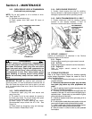
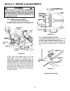
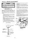
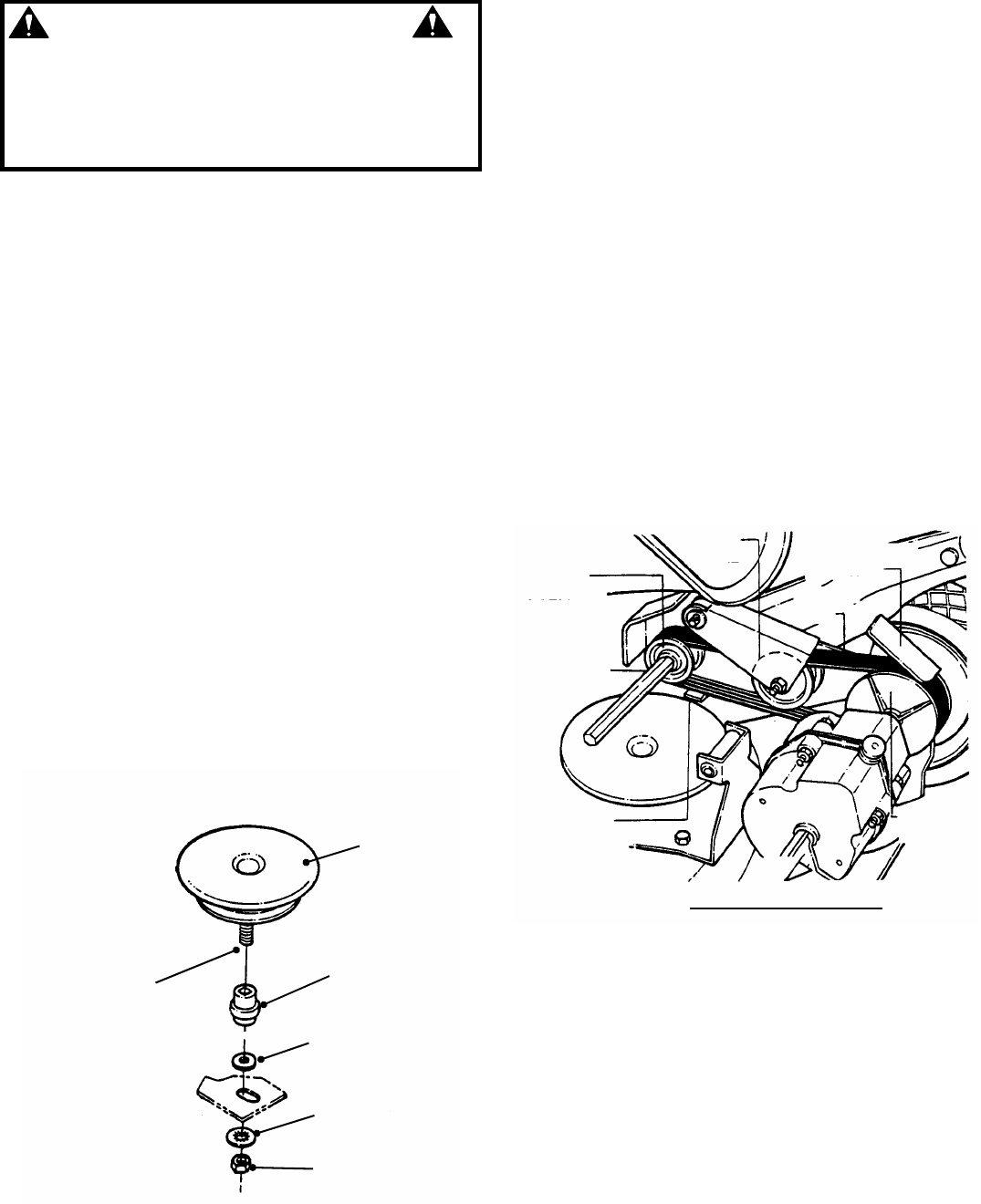
5. Hold the slotted end of the drive disc bolt with a
screwdriver and remove the nut and internal tooth
lock washer. See Figure 4.16.
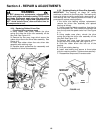
6. Remove the belt cover located under deck.
7. Lift the drive disc up and remove worn belt.
8. Loop one end of new belt over engine pulley and
insert the other end through slot in deck. See Figure
4.15.
PULLEY POSITION
FIGURE 4.16
9. Loop the belt around the pulley on the bottom of
the drive disc.
10. Reinstall drive disc and retaining hardware.
IMPORTANT: 1) The square shoulder of the drive
disc bolt must fit into the square hole of the bushing.
2) The square end of bushing must fit into the
bracket slot.
11. Reinstall belt cover and tighten bolts securely.
12. Reinstall blade hub and cutter blade.
Recommended torque for blade cap screw is 40 ft. lbs.
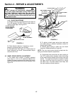
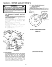
4.4.2. Transmission Poly-V Belt Replacement
1. Remove the driven disc. Refer to Section on
“Replacing Driven Disc Rubber Ring” for procedure.
2. Note the routing of the old belt around the three
pulleys before removing it. See Figure 4.17.
3. Place new Poly-V Belt over end of hex shaft and
onto driven pulley.
4. Work belt onto top of idler pulley.
5. Twist belt sideways and pull it upward between
the differential bracket and drive pulley and then
down into the pulley groove. Make sure the Poly-V
Belt is above belt guide. See Figure 4.17.
FIGURE 4.17
IDLER
PULLEY
DRIVE
PULLEY
DIFFERENTIAL
BRACKET
POLY-V
BELT
DRIVEN
PULLEY
BELT GUIDE
HEX SHAFT
ROUTING OF POLY-V BELT
DRIVE DISC
BUSHING
BOLT RETAINER
INTERNAL TOOTH
LOCKWASHER
NUT
SLOT IN END
OF DRIVE DISC
BOLT
DECK BRACKET
(PARTIALLY SHOWN)