7
Chapter 7 Location and Function of Parts and Controls 99HDC-900/950/930 Series Product Information Manual
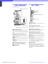
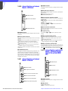
7-4-8 Internal Switches and Internal
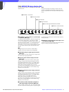
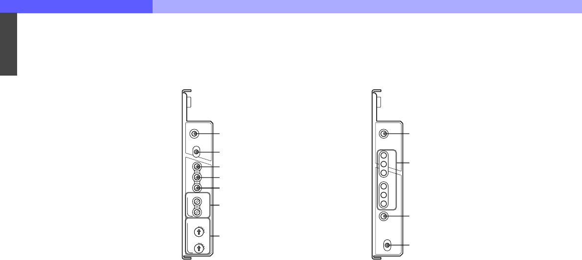
Boards – AVP Board
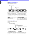
a POWER indicator
The LED is lit when the power voltage inside the board
is normal.
b PGM1/MIX/PGM2 (program audio) selector
To select the program audio to be sent to the headset
connected to the intercom connector on the front
panel:
PGM1: Program audio 1
MIX: Program audio 1 + Program audio 2
PGM2: Program audio 2
c PGM1 LEVEL (program 1 audio level) control
To adjust the mixing volume of the PGM1 audio signal
at the headset connected to the intercom connector on
the front panel
d PGM2 LEVEL (program 2 audio level) control
To adjust the mixing volume of the PGM2 audio signal
at the headset connected to the intercom connector on
the front panel
e SIDE TONE control
To adjust the volume of your voice to be supplied to the
headset connected to the intercom connector on the
front panel
f 2WIRE CANCEL controls
When using the 2-wire intercom system, adjust the
controls to minimize the side tone level on the producer
line (PROD) and engineer line (ENG).
g MIC AMP GAIN (microphone amplifier gain)
controls
These controls permit you to adjust the amplifier gain
of the camera so that the proper audio levels can be
obtained appropriate to the sensitivities of the
microphones (MIC1 and MIC2) connected to the
camera.
The adjustment is valid when no connection is made to
the MIC REMOTE connector on the rear panel of this
unit or, if the connection is made, when the internal
setting is selected for the connector (pins 8 and 15 are
set to a high level). The adjustment range is from
NORM (60 dB) to MIN (20 dB) in 10-dB steps. This
switch changes the gain of a microphone amplifier in
the camera.
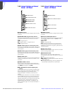
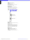
7-4-9 Internal Switches and Internal
Boards – DTX Board
a POWER indicator
The LED is lit when the power voltage inside the board
is normal.
b OPTICAL CONDITION indicators
The corresponding LEDs light to show the condition of
optical signal reception at this unit (CCU) and the
camera (CHU):
Green: Good
Yellow: Low optical level
Red: Extremely low optical level, or disconnection
If communication with the connected camera is not
established, all the three CHU green, yellow and red
indicators go dark.
c CHU LOCK indicator
The LED is lit when communication with the connected
camera is being properly made.
d RETURN SET switch
Select the type of the return video signal to be
connected to the RET1, RET2 and RET3 connectors of
this unit:
HD: HD-SDI signal (local setting)
REM (remote): Signal selected on the MSU-700A/ 750
Master Setup Unit
SD: SD signal (local setting). Switching between SD
SDI and VBS is made with an internal switch.
AVP
POWER
PGM1
LEVEL
PGM2
LEVEL
SIDE
TONE
PROD
ENG
MIN
MIN
NORM
NORM
MIC2
MIC1
MIC AMP GAIN
2WIRE CANCEL
INTERCOM
PGM1
MIX
PGM2
1 POWER indicator
2 PGM1/MIX/PGM2 selector
3 PGM1 LEVEL control
4 PGM2 LEVEL control
5 SIDE TONE control
6 2WIRE CANCEL controls
7 MIC AMP GAIN controls
DTX
POWER
RETURN SET
OPTICAL
CONDITION
HD
REM
SD
CCU
CHU
CHU
LOCK
1 POWER indicator
2 OPTICAL CONDITION indicators
3 CHU LOCK indicator
4 RETURN SET switch


