


5(E)
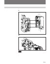
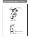
1 Battery attachment section
Attaches a BP-L60/L60A/L90/L90A Battery Pack, a
DC-L1 Battery Adaptor containing an NP-1B/1A
Battery Pack, or a DC-L90 Battery Adaptor containing
a BP-90A/90 Battery Pack.
For details on battery attachment, refer to the operation
manual of the camcorder.
2 RET (return video) button
Pressing this button allows you to use the viewfinder
on the camcorder as a monitor for portable VTR. In
input mode, this button can be used as a substitute for
the RET button on the lens.
3 VTR START button
In input mode, this button controls record and pause
operations on the camcorder.
4 EARPHONE jack
Connects an earphone for monitoring of the sound
signal recorded by a portable VTR.
5 VTR connector (26-pin)
Inputs and outputs video signals, audio signals, or
control signals from the CAMERA connector on a
portable VTR.
Power is not supplied from the portable VTR through
this connector to either the CA-702/702P itself or the
camcorder.
6 DC IN (DC power input) connector (XLR type,
4-pin, male)
Connects an AC adaptor or an external battery through
a DC output cable. Power input to the CA-702/702P is
supplied to the camcorder. When the CA-702/702P is
connected to a camcorder, the DC IN connector on the
back of the camcorder cannot be used. The DC IN
connector can thus be used in place of the one on the
camcorder. In this case, the power supply to the
camcorder remains continuous even when power to the
CA-702/702P is turned off.
7 DC OUT (DC power output) connector (4-pin)
Supplies power to an optional WRR-860A UHF
Synthesized Diversity Tuner. Use this connector when
an optional battery and tuner are attached to the CA-
702/702P and the tuner’s power cord cannot reach the
DC OUT connector on the back of the camcorder.
8 POWER/MODE switch
This switch turns the power to the CA-702/702P on
and off and selects the operation mode.
ON/OUT: Turns on the CA-702/702P. In this mode,
the camcorder outputs video and audio signals to a
portable VTR and SDI signals from the VIDEO/
SDI OUT connector (output mode).
ON/IN: Turns on the CA-702/702P. In this mode, an
external video input signal (composite or SDI) can
be recorded on the camcorder (input mode).
OFF: Turns off the CA-702/702P.
Notes
• When attached to a DVW-700, DVW-700WS, or
DNV-5, the CA-702/702P cannot be used in input
mode.
• The POWER/MODE switch controls the power to the
CA-702/702P alone and cannot be used to
simultaneously turn on or off the camcorder or the
CA-702/702P’s DC power output.
9 SDI/COMPOSITE switch
Selects the video signal to be input to the VIDEO/SDI
IN connector.
SDI: SDI signal
COMPOSITE: Composite signal
Set the SDI/COMPOSITE switch to SDI to output an
SDI signal from the VIDEO/SDI OUT connector.
Note
The SDI/COMPOSITE switch setting does not affect
the video output signal to the VTR connector.
!º VIDEO/SDI OUT (video output) connector
(BNC-type)
Outputs the video signal. In input mode, outputs the
active-through signal fed from the VIDEO/SDI IN
connector.
In output mode, outputs the picture or playback video
signal from the camcorder only when the SDI/
COMPOSITE switch is set to SDI.
!¡ VIDEO/SDI IN (video input) connector (BNC-
type)
Inputs the external video signal. This connector is
terminated with a 75-ohm resistor inside the CA-702/
702P. For this reason, a terminator need not be
attached to the VIDEO/SDI connector.
The setting of the SDI/COMPOSITE switch can be
changed according to the input signal type.
This connector cannot be used in output mode.