Function and Location of Parts and Controls
10
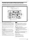
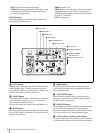
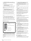
A REFERENCE INPUT connectors (BNC type)
Accept reference signals (black burst signal) for external
synchronization.
B RET-1/RET-2 (return video signal 1/2)
connectors (BNC type)
Accept return video signals from two different systems.
For details on the selection of RET-1 and RET-2, refer to
Operation Manual that came with the camera or camera
adaptor.
C RET-3/PROMPTER (return video signal 3/
prompter) connectors (BNC type)
Accept a return video signal or a teleprompter signal.
For details on the selection of RET-3, refer to Operation
Manual that came with the camera or camera adaptor.
To set this connector to the PROMPTER output, it is
required to change the setting in the internal board.
For details on the internal boards, consult your nearest Sony
dealer.
D COAX (coaxial) connector (BNC type)
Accepts and supplies signals from/to the video camera
using a coaxial cable. Power is not supplied to the
camera and a camera adapter through this connector.
To use this connector, it is required to change the setting of the
internal board. For details, consult your nearest Sony dealer.
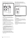
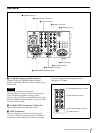
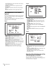
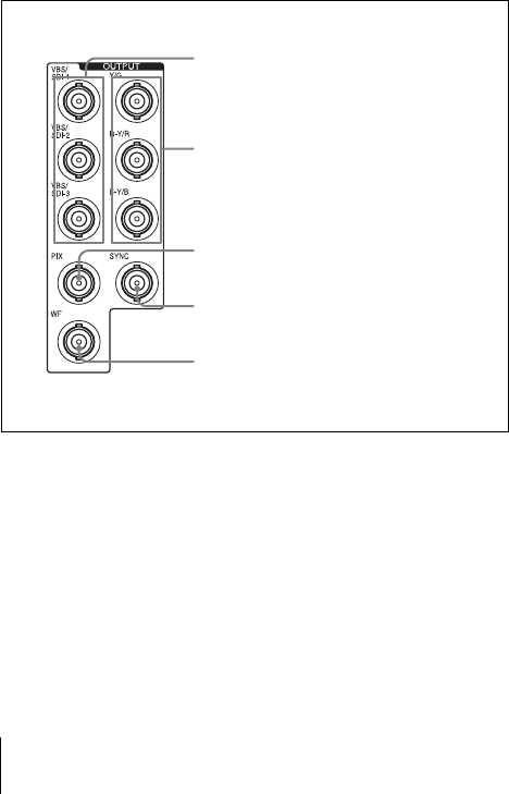
d OUTPUT connectors
A VBS/SDI-1/VBS/SDI-2/VBS/SDI-3 (composite
video signal 1/2/3 output) connectors (BNC type)
Supply the signal from the video camera in composite or
SDI format.
Use the switch on the internal board to select the signals
to be output.
For details on the internal boards, consult your nearest Sony
dealer.
B Y/G, R-Y/R, B-Y/B (component video signal /
RGB output) connectors (BNC type)
Supply the component signals or the R, G, and B signals
for the chroma keyer from each connector.
Use the switch on the internal board to select the signals
to be output.
For details on the internal boards, consult your nearest Sony
dealer.
C PIX (picture monitor output) connector (BNC
type)
Supplies a video signal or video and character signals
together to a picture monitor.
When using the RCP-D50 Remote Control Panel, you
can select the signal output from the PIX connector
using the MONITOR SELECT button on the menu of
the RCP-D50. When the signal output from the PIX
connector changes, the waveform output on the
waveform monitor also changes.
D SYNC connector
Connect to the synchronous signal input connector on a
waveform monitor or picture monitor
E WF (waveform monitor output) connector (BNC
type)
Supplies a video signal to a waveform monitor.
When using the RCP-D50 Remote Control Panel, you
can select the signal output from the PIX connector
using the MONITOR SELECT button on the menu of
the RCP-D50. Changing the signal output from the WF
connector simultaneously changes the picture on the
picture monitor.
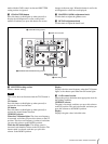
e REMOTE (RCP (remote control panel) remote)
connector (10-pin)
Connects to the RCP-D50 Series Remote Control Panel
with an optional CCA-7 connecting cable to transmit/
receive control signals.
f INTERCOM/TALLY/PGM (program audio)
connector (D-sub, 25-pin)
Inputs/outputs intercom, tally, or program audio signals.
Connects to an intercom, tally, or program audio
connector of an intercom system.
g MIC REMOTE (microphone remote control)
connector (D-sub, 15-pin)
Connects to an external control unit such as an audio
mixer. With the connected unit, you can set the
microphone input level of the video camera to –60, –50,
–40, –30, or –20 dB.
h WF MODE (waveform monitor mode)
connector (4-pin)
Connects to the corresponding connector on a waveform
monitor to allow the sequential monitoring of signals.
A VBS/SDI-1/VBS/SDI-2/VBS/SDI-3
connectors
B Y/G, R-Y/R, B-Y/B connectors
C PIX connector
D SYNC connector
E WF connector


