


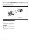
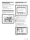
Self-Diagnostics
16
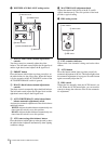
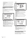
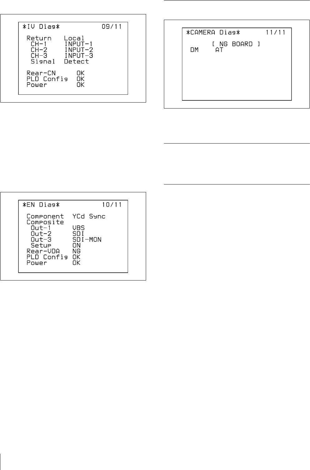
IV board
Return: Setting status of the return signal input
connectors to the return channels from 1 to 3
Return Signal: Status of the return video input signal
Rear CN: Power supply status of the CN board on the
rear
PLD Config: Configuration completion status of the
PLD mounted on the IV board
Power: Power supply status of the IV board
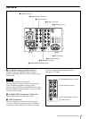
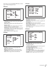
EN board
Component: Setting status of the component output
signal from the OUTPUT connector and status of the
sync signal added to the component Y/G output signal
from the OUTPUT connector
Composite Out-1: Signal type from composite output
connector 1 (VBS/SDI)
Composite Out-2: Signal type from composite output
connector 2 (VBS/SDI)
Composite Out-3: Signal type from composite output
connector 3 (VBS/SDI)
Composite Setup: Setup settings to be added to the
VBS signal
Rear VDA: Power supply status of the VDA board on
the rear
PLD Cofig: Configuration completion status of the
PLD mounted on the EN board
Power: Power supply status of the EN board
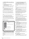
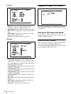
Diagnostics Page of the Camera
The results of the diagnosis of each board of the camera
are displayed.
Exiting the Self-diagnostic Mode
Display the last “ROM Version” page, and then press the
CHARACTER button again.
When an Error Occurs
The error message is displayed on the picture monitor. In
such a case, display the self-diagnostics page
corresponding to the board where the error has occurred
by pressing the CHARACTER button.