


21
Location and Function of Parts
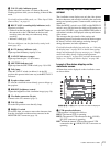
Chapter 1 Overview
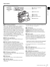
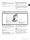
f TALLY (tally) indicator (green)
Flashes when the camcorder is in Interval Rec mode.
Flashing quickens while you are shooting in Interval Rec
mode.
For details on Interval Rec mode, see “Time-Lapse Video
(Interval Rec)” on page 63.
g REC/TALLY (recording/tally) indicators (red)
Functions as follows.
• Flashes from the time when you press the REC button on
the camcorder or the VTR button on the lens until
recording starts, then stay on continuously during
recording.
• Indicates a fault (page 125).
The lower indicator can also function by setting in the
menu
(page 87).
h BATT (battery) indicator (red)
Lights up when the battery capacity is low.
i GAIN UP indicator (orange)
Lights up when the gain is 3 dB or more.
j SHUTTER indicator (red)
Lights up when the SHUTTER switch (page 10) is ON.
k Tally lamp
When the TALLY switch (see below) is in the ON
position, this operates in the same way as the REC/TALLY
indicators.
l Eyepiece release catch
To view the viewfinder screen directly, press to hinge up
the eyepiece.
m BRIGHT (brightness) control
Adjusts the brightness of the viewfinder image (page 30).
n Viewfinder connector (20-pin)
Connect to the VF connector (page 9).
o TALLY switch
Set to the ON position to use the tally lamp.
p DISPLAY switch
Set to OFF when you want to remove the character data
from the viewfinder and the monitor connected to the
MONITOR OUT connector
(page 14).
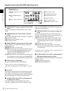
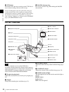
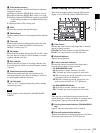
Status display on the viewfinder
screen
The viewfinder screen displays not only the video picture
but also characters and messages indicating the camcorder
settings and operating status, a center marker, a safety zone
marker, etc.
When the MENU switch is set to OFF and the DISPLAY
switch is set to ON, the items for which an ON setting was
made in the VF DISP 1 page of the OPERATION menu or
with related switches are displayed at the top and bottom
of the screen.
The messages that give details of the settings and
adjustment progress and results can also be made to appear
for about 3 seconds while settings are being changed,
during adjustment, and after adjustment.
For details about the display item selection, see “Selecting
the display items” on page 98. For details about setting
change and adjustment progress messages, see “Display
modes and setting change confirmation/adjustment
progress messages” on page 99. For details about marker
display, see “Setting the marker display” on page 100.
Layout of the status display on the
viewfinder screen
All items that can be displayed on the viewfinder screen
are shown below.
a VTR operation indicators
VTR operation is displayed as follows:
REC1: The internal VTR is operating.
REC2: The external VTR connected to the (i.LINK)
DV OUT connecter is operating.
REC
1
2
: Both the internal VTR and the external VTR
connected to the
(i.LINK) DV OUT connector are
operating.
24
PARA
DSR-400 #30001
05/ 03/23 01:43
WHITE NG
LEVEL TOO HIGH
TCG 00 : 00 : 00 : 00
LOW LIGHT
DVCAM
EXT
IV
0dB
1/1000
15-10
F5.6
W:A
D5600
1
SHOT ID(1 - 4)
REC
3. 2K
16: 9
4: 3
16. 0V
DC IN
EX
6, 7, wa, ws, and wd appear only when color bars are displayed.