


Chapter 1 Overview 11
(GB)
Chapter 1
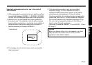
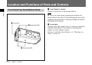
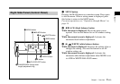
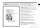
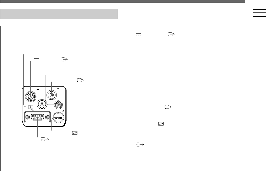
Rear Panel
VIDEO OUT
DC IN/VBS
REMOTE
LENS
TRIG IN
MENU LOCK
OFF ON
RGB/SYNC
1 MENU LOCK ON/OFF switch
2 DC IN/VBS connector
3 TRIG IN connector
4 LENS connector
5 VIDEO OUT connector
6 REMOTE connector
7 RGB/SYNC connector
1 MENU LOCK ON/OFF switch
When this switch is set to ON, the menu is not displayed on
the screen even if you press the MENU button.
2 DC IN/VBS (DC input/video signal output)
connector (12-pin)
Connects to the CMA-D2/D2MD/D2CE/D2MDCE camera
adaptor. Inputs the DC power and outputs the video signal.
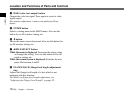
3 TRIG IN connector (BNC type)
Connects to a commercially available slave unit by
converting to BNC type in strobe mode.
4 LENS connector (6-pin)
Connects to a lens control cable when attaching the zoom
lens especially designed for this camera.
5 VIDEO OUT connector (BNC type)
Outputs a composite video signal.
6 REMOTE connector (mini DIN 8-pin)
Connects to the RM-C950 remote control unit (not
supplied).
7 RGB/SYNC connector (D-sub 9-pin)
Outputs RGB signals and their respective sync signals.
Use the CCXC-9DB/CCXC-9DD/CCMC-9DS connecting
cable for the connections.