


36
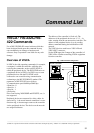
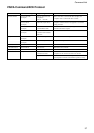
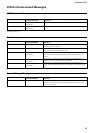
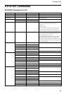
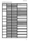
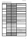
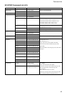
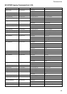
Command List
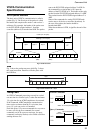
The VISCA RS-422 connector pin
assignments
12345
VISCA RS-422
6789
Pin No. Function
1TXD IN+
2TXD IN–
3 RXD IN+
4 RXD IN–
5 GND
6TXD OUT+
7TXD OUT–
8 RXD OUT+
9 RXD OUT–
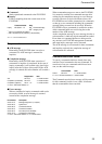
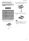
Using the VISCA RS-422 connector plug
1 Grasp both ends of the VISCA RS-422 connector
plug and pull it away from the rear panel of the
camera, as shown in the illustration.
12
3
4
5
6
78
9
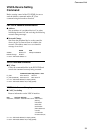
Using the VISCA RS-422
connector pin assignments
2
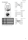
Insert a wire (AW G Nos. 28 to 18) into the desired
wire opening on the plug, and tighten the screw for
that wire using a flat-head screwdriver.
3 Insert the VISCA RS-422 connector plug into the
VISCA RS-422 connector on the back of the
camera.
12
3
4
56
78
9
Notes
•In order to stabilize the voltage level of the signal,
connect both ends to GND.
•Do not make a VISCA RS-232C connection when
there is already an existing VISCA RS-422
connection.
Flat-head screwdriver
Wire