


39
Location and Functions of Parts and Controls
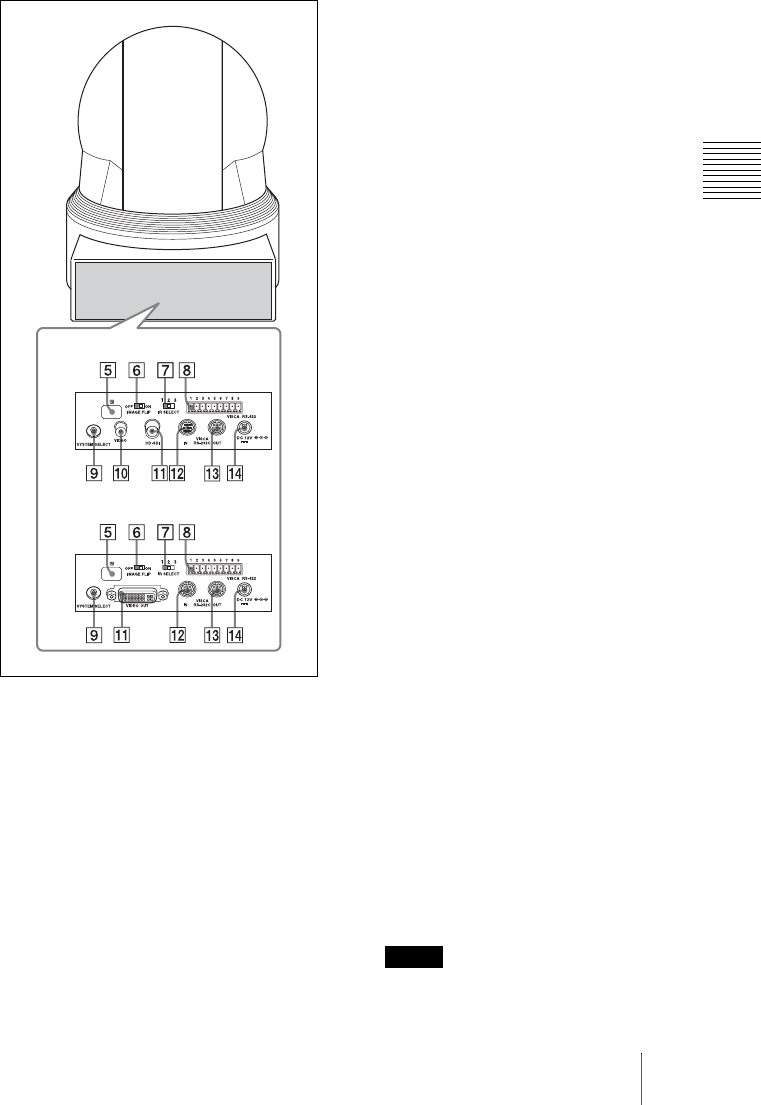
Overview
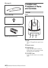
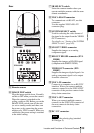
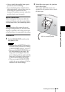
Rear
E Remote sensors
F IMAGE FLIP switch
Flips the image upside down. Normally
set this to OFF when you use the camera.
When the camera is attached to the
ceiling, set this to ON. Before you set the
IMAGE FLIP switch, turn off the unit
(or set to standby mode) and then, turn
the power on by connecting the power
adaptor or by VISCA control. When you
switch this, the preset setting is returned
to the initial setting.
G IR SELECT switch
Select the camera number when you
operate multiple cameras with the same
remote commander.
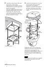
H VISCA RS-422 connector
To communicate via RS-422, use this
connector.
Use the supplied VISCA RS-422
connector plug.
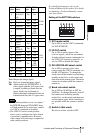
I SYSTEM SELECT switch
Used for selecting the video format of
the signal to be output from the VIDEO
OUT connectors.
For details, see “Setting of the SYSTEM
SELECT switch” (page 40).
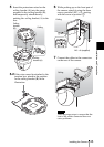
J SD OUT VIDEO connector
Supplies the images as an analog
component signal.
K HD OUT HD-SDI connector (EVI-
H100S)
Supplies the images as HD-SDI signal
(compliant with SMPTE 292M).
VIDEO OUT connector (EVI-
H100V)
Supplies the image as digital signals. An
analog component signal is also output
from this connector.
L VISCA IN connector
Connect to a computer via an RS-232C
interface. When you connect multiple
cameras, connect it to the VISCA OUT
connector of the previous camera in the
daisy chain connection.
M VISCA OUT connector
When you connect multiple cameras,
connect it to the VISCA IN connector of
the next camera in the daisy chain
connection.
N DC 12 V connector
Use only the polarity plug (standard
JEITA/type 4).
EVI-H100S
EVI-H100V
Note