


3-3 (E)
HDCU-900 MM
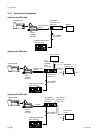
3-1-4. Initialization Settings
HDCU-900
n
When changing the switch settings from the customer’s
setting positions, it is recommended to write down the
customer’s setting positions in the following table. After
completing the adjustment, be sure to return the switches
to the customer’s setting positions.
Board Switch Setting Customer
during setting
adjustment
AT-141 S102 to 105 S105-5 only
is ON
All others
are OFF
S110 REMOTE
S301 0 dBu
S302 0 dBu
S401 0 dBu
S402 0 dBu
S403, 41 RTS
S404, 504 4W
S501 OFF
S502 2ch
S503 PROD
S601 LOCAL
S602 BB
RC-86 S804 422YC
S805 REMOTE
IF-789A
*1
/789P
*2
S101-1 ON
S101-2 SMPTE
S201 OFF
S202 ON
S706 3WAVE
Set the switches other than the above to the state when shipped from the
factory.
For details of the switch settings, refer to Section 1-5, “Settings of Switches
and Controls on Boards” of the separate Installation and Maintenance
Manual.
*1 : for UC
*2 : for CE
When using the MSU-700A:
. Power supply and signal selector block
ALL button → OFF (Dark)
CAM PW button → ON (Lit)
TEST1 button → OFF (Dark)
TEST2 button → OFF (Dark)
BARS button → OFF (Dark)
CLOSE button → ON (Lit)
. Camera/CCU circuit ON/OFF block
DETAIL OFF button → OFF (Lit)
KNEE OFF button → ON (Dark)
AUTO KNEE button → OFF (Dark)
MATRIX OFF button → OFF (Lit)
. AUTO SETUP block
LEVEL button → OFF (Dark)
WHITE button → OFF (Dark)
BLACK button → OFF (Dark)
. Others
GAMMA OFF button → OFF (Dark)
MASTER GAIN selector button → 0
When using the MSU-750:
. Power supply and signal selector block
ALL button → OFF (Dark)
CAM PW button → ON (Lit)
TEST button → OFF (Dark)
BARS button → OFF (Dark)
CLOSE button → ON (Lit)
. AUTO SETUP block
LEVEL button → OFF (Dark)
WHITE button → OFF (Dark)
BLACK button → OFF (Dark)
. Others
GAMMA OFF
*
→ ON
(Not highlighted)
MASTER GAIN
*
→ 0 (0 dB)
* : Press the function button and select it on the function menu display.
3-1. Preparation