


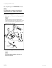
3-4 (E)
HDCU-900 MM
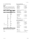
3-2. Audio System Adjustment
3-2-1. Microphone Level Adjustment
Measures : Oscilloscope, Audio oscillator
Note
This adjustment is described on the premise that the output
impedance of the audio oscillator is 600 Z.
Preparation
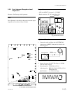
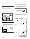
. Board extension : AT-141 board (front side)
. Board extension : AU-271 board (CAMERA side)
. S126 (MIC CH-1 LEVEL)/AT-141 board panel side →
MIN
. S128 (MIC CH-2 LEVEL)/AT-141 board panel side →
MIN
. S402 (E-3)/AT-141 → 0 dBu
. S401 (D-3)/AT-141 → 0 dBu
Adjustment Procedure
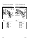
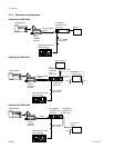
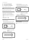
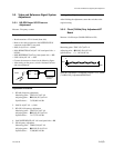
1. MIC1 level adjustment
Input a sine wave of 1 kHz, 220 mV p-p (_20 dBu)
from the audio oscillator to 20-pin (X), 19-pin (Y) and
18-pin (G) of the extension board (camera side).
2. Measuring point : TP401 (E-3)/AT-141 or AUDIO
OUTPUT CH-1 connector/HDCU
rear panel
Adjusting point : 1RV401 (E-2)/AT-141
Specifications : A = 1100 ±50 mV p-p
3. Remove the cable that is connected in step 1.
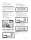
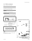
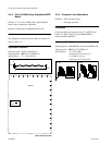
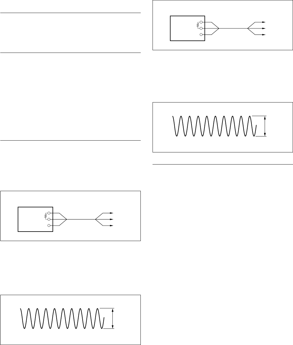
4. MIC2 level adjustment
Input a sine wave of 1 kHz, 220 mV p-p (_20 dBu)
from the audio oscillator to 15-pin (X), 16-pin (Y) and
17-pin (G) of the extension board (camera side).
5. Measuring point : TP402 (D-3)/AT-141 or AUDIO
OUTPUT CH-2 connector/HDCU
rear panel
Adjusting point : 1RV402 (D-2)/AT-141
Specifications : B = 1100 ±50 mV p-p
Setting after Adjustment
S401 (D-3), S402 (E-3)/AT-141 → Return to the original
setting.
600 Z
Audio oscillator
GND GND
Y
X
A
600 Z
Audio oscillator
GND GND
Y
X
B
3-2. Audio System Adjustment