


16
Mode Setting
1
1
3
3
2
2
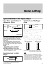
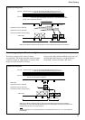
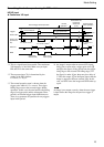
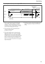
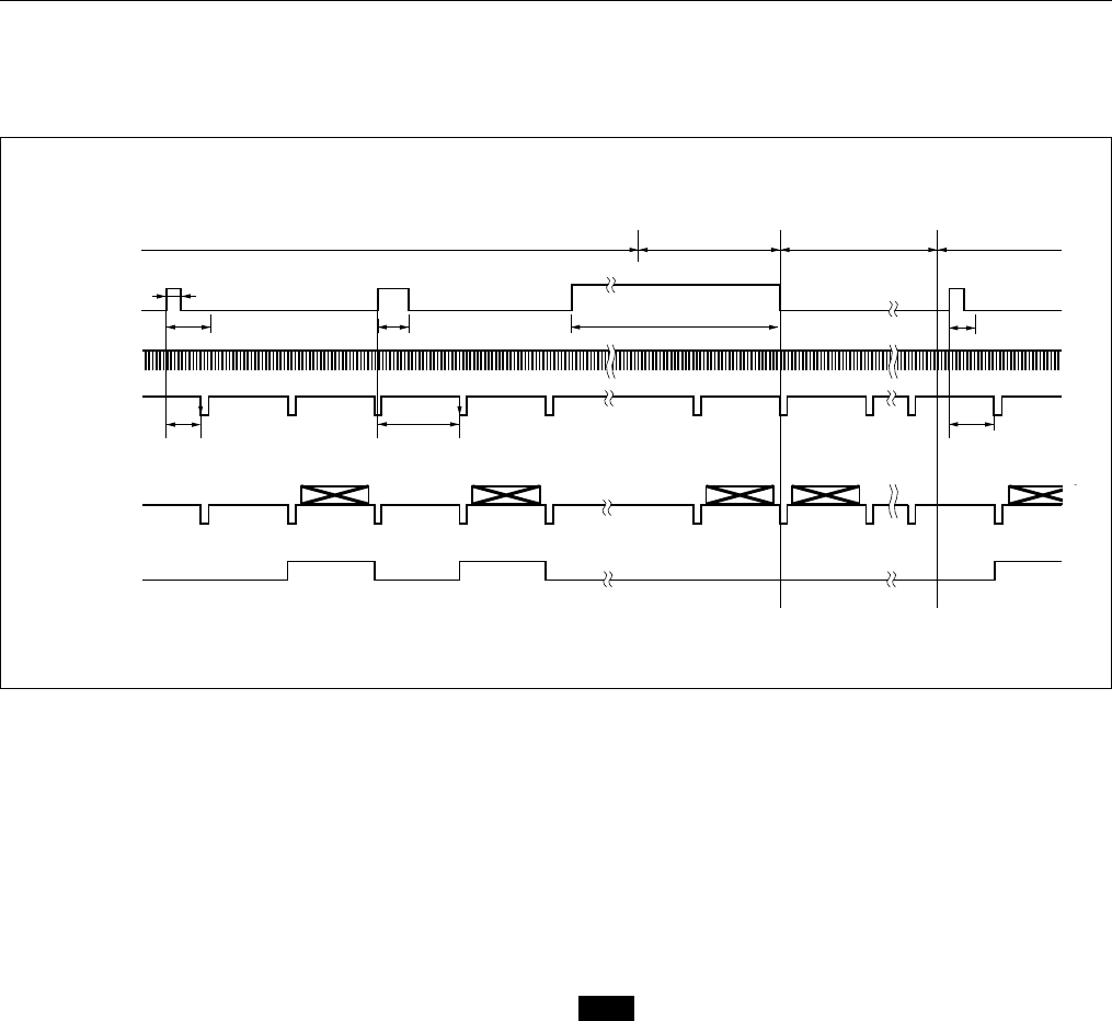
For setting the shutter speed using the DIP switches
HD/VD input
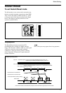
◆ Continuous VD input
*1 This is a signal input from outside. The continuous
VD frequency is one field. Make sure you input
HD and VD at the same time.
*2 The exposure time (Te) is determined by the
setting of the DIP switches.
For details, see Page 9.
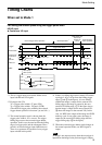
*3 The normal operation state is chosen when the
trigger pulse width is 1/3 s or more. The trigger
falling edge restores the external trigger shutter
operation. In this case, the area between the falling
edge of a trigger pulse and the subsequent 50 ms
period is an external trigger input inhibition area.
There is no guarantee of operation for any triggers
input in this period.
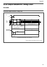
External trigger shutter operation
Normal
operation*
3
Mode transition state
External input
inhibition area
(50 ms)
External trigger
shutter operation
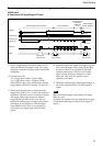
Exposure time (Te)*
2
Exposure time
(Te)*
2
Trigger pulse width*
3
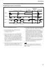
T: T=under 10 ms*
4
250 H (EIA)
293 H (CCIR)
Exposure time (Te)*
2
100
µ
s to 250 ms
T: T=10 ms or more*
4
T: T=10 ms or
more*
4
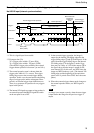
Trigger*
1
External HD*
1
Video out
WEN
External VD*
1
(Continuous
VD)
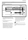
*4 An image is output when an external VD signal
falls 10 ms or more after a trigger pulse rises (2
and 3 in the figure). If the period from the trigger
rising edge to the external VD falling edge (T in
the figure) is under 10 ms, there may be a delay of
1 VD in the output. (1 in the figure shows that the
image is output for the next external VD). In this
case, see WEN since the image and WEN make up
a pair.
Note
An image is not output correctly when the next trigger
is input before the image for the previous trigger is
output.
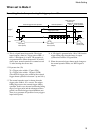
250 H (EIA)
293 H (CCIR)