


17
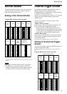
Mode Setting
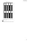
For setting the shutter speed using the DIP switches
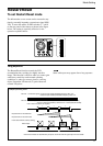
HD/VD input
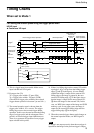
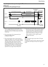
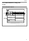
◆ Continuous HD input/Single VD input
*1 This is a signal input from outside. Make sure to
input both HD and VD signals in this case. Input
the signal so that the VD phase aligns with the HD
falling edge.
*2 The exposure time (Te) is determined by the
setting of the DIP switches.
For details, see Page 9.
*3 The normal operation state is chosen when the
trigger pulse width is 1/3 s or more. (By entering a
continuous VD in this section, an image is output.)
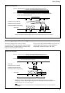
The trigger falling edge restores the external
trigger shutter operation. In this case, the area
between the falling edge of a trigger pulse and the
subsequent 50 ms period is an external trigger
input inhibition area. There is no guarantee of
operation for any triggers input in this period.
1
1
2
2
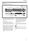
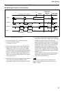
*4 Input the external VD within the period of 10
ms to
75 ms after the trigger rising edge (1 and 2 in
the figure). There is no guarantee of operation
when any other input is selected. If an invalid
signal is input, the input is changed to a valid
signal, and after several V signals, normal
operation will resume.
Note
Make sure that the trigger signal and the VD signal
make up a pair.
An image is not output correctly when the next trigger
is input before the image for the previous trigger is
output.
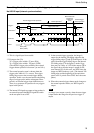
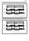
External trigger shutter operation
Normal operation*
3
Mode transition state
External input
inhibition area
(50 ms)
External trigger
shutter operation
Exposure time (Te)*
2
Exposure time
(Te)*
2
Trigger pulse width*
3
T: T=10 ms to 75 ms*
4
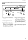
Trigger*
1
External HD*
1
Video out
WEN
External VD*
1
(Single VD)
min.10 ms
100
µ
s to 250 ms
250 H (EIA)
293 H (CCIR)
250 H (EIA)
293 H (CCIR)