


Interface Assignments
3-3
Installation
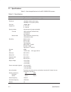
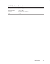
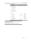
Table 3–4.AUX Connector Pin Assignment
Pin Signal Name I/O Trigger Interface
1 MCK RTN
2 Horizontal Drive RTN
3 Vertical Drive RTN
4 Pixel Clk Out RTN
5 Shutter RTN
6 Shutter Monitor RTN
7 Internal/External RTN
8 GND
9 MCK IN I SN75124N
10 Horizontal Drive I Negative SN75124N
11 Vertical Drive I Negative SN75124N
12 Pixel Clk Out O SN75123N
13 Shutter CMD I SN74LS14N
14 Shutter Monitor OUT O Negative SN75123N
15
Internal/External I
Note: Connector Information
External mode: short 7 pin––––15 pin
Internal mode: open 7 pin––––15 pin
Connectors: Dsub 15 pin female connector, #4-40 (cable side)