


Tables
viii
Figures
1–1 MC-1000WU-20A Interface Options and Mode Selection 1-3. . . . . . . . . . . . . . . . . . . . . . . . . . .
2–1 Input Interface Circuit of VD, HD, and MCK 2-4. . . . . . . . . . . . . . . . . . . . . . . . . . . . . . . . . . . . . . .
2–2 Output Interface Circuit of Pixel and Shutter Monitor 2-4. . . . . . . . . . . . . . . . . . . . . . . . . . . . . . .
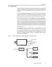
A–1 Functional Block Diagram A-2. . . . . . . . . . . . . . . . . . . . . . . . . . . . . . . . . . . . . . . . . . . . . . . . . . . . . .
B–1 TV Internal Mode (see Note) B-2. . . . . . . . . . . . . . . . . . . . . . . . . . . . . . . . . . . . . . . . . . . . . . . . . . . .
B–2 TV External Mode B-3. . . . . . . . . . . . . . . . . . . . . . . . . . . . . . . . . . . . . . . . . . . . . . . . . . . . . . . . . . . . .
B–3 The Relationship of Vertical Sync Out and Mechanical Shutter or Strobe Light B-3. . . . . . . .
B–4 The Relationship of Horizontal Drive Input and Video Output B-4. . . . . . . . . . . . . . . . . . . . . . . .
B–5 Shutter Internal Mode B-4. . . . . . . . . . . . . . . . . . . . . . . . . . . . . . . . . . . . . . . . . . . . . . . . . . . . . . . . . .
B–6 Shutter External Mode B-5. . . . . . . . . . . . . . . . . . . . . . . . . . . . . . . . . . . . . . . . . . . . . . . . . . . . . . . . .
B–7 The Relationship of VD Input and HD Input B-5. . . . . . . . . . . . . . . . . . . . . . . . . . . . . . . . . . . . . . .
B–8 HD Input Waveform B-6. . . . . . . . . . . . . . . . . . . . . . . . . . . . . . . . . . . . . . . . . . . . . . . . . . . . . . . . . . .
B–9 The Relationship of VD Input and C-Sync B-6. . . . . . . . . . . . . . . . . . . . . . . . . . . . . . . . . . . . . . . .
Tables
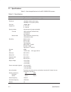
2–1 Specifications 2-2. . . . . . . . . . . . . . . . . . . . . . . . . . . . . . . . . . . . . . . . . . . . . . . . . . . . . . . . . . . . . . . .
3–1 Auto Iris Connector Pin Assignment 3-2. . . . . . . . . . . . . . . . . . . . . . . . . . . . . . . . . . . . . . . . . . . . .
3–2 Power Connector Pin Assignment 3-2. . . . . . . . . . . . . . . . . . . . . . . . . . . . . . . . . . . . . . . . . . . . . . .
3–3 Video Connector (BNC Connector) 3-2. . . . . . . . . . . . . . . . . . . . . . . . . . . . . . . . . . . . . . . . . . . . . .
3–4 AUX Connector Pin Assignment 3-3. . . . . . . . . . . . . . . . . . . . . . . . . . . . . . . . . . . . . . . . . . . . . . . .