9
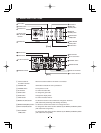
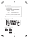
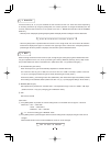
㽽 DC IN 12V terminal
Accept a DC power input (12V).
㽾Y/G terminal
Outputs Y or G. (BNC connector)
㽿P
B/B terminal
Outputs P
B or B. (BNC connector)
㾀P
R/R terminal
Outputs P
R or R. (BNC connector)
㾁REMOTE terminal
To connect to a RS-232C device for remote control function.
㾂EXT. SYNC terminal
Used when the camera output signal is synchronized to an external signal.
(BNC connector)
㾃SYNC OUT terminal Output terminal for synchronization signal. (BNC connector)
㾄HD-SDI terminal
Video signal output terminal for HD-SDI format video signal. (BNC connector)
㾅KEY LOCK switch Enables/disables buttons
FORMAT switch Switches between 59.94i and 50i.
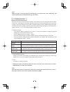
㽵 to 㽼.
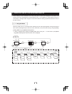
Lens
(option)
IK-HD1H
䋨
option
䋩
Camera
Control unit
Camera Cable
for IK-HD1E
䋨
option
䋩
HD monitor
analog TV (option)
DC power supply
(option)
DC power supply
(option)
DC IN 12V
Y/P
B/PR
Three Coaxial
Cables 75
(option)
㱅
IK-HD1E
5 CONNECTION
5
5. 1 -1 Analog Connection
1 Standard Connection
Lens
(option)
IK-HD1H
䋨
option
䋩
Camera
Control unit
Camera Cable
for IK-HD1E
䋨
option
䋩
HD monitor
digital TV (option)
DC IN 12V
HD-SDI
One Coaxial
Cable 75
(option)
㱅
IK-HD1E
5. 1 -2 Digital Connection
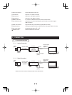
* Please use a low conductor resistance cable for HD-SDI terminal.


