


1717
Network Deployment
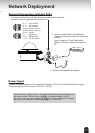
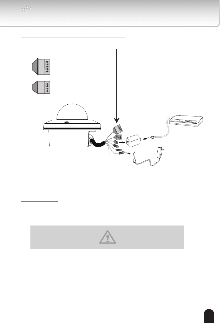
General Connection (without PoE)
N.C.
N.C.
N.C.
AC24V
AC24V
POW
ER
C
O
LL
I
S
ION
L
I
N
K
RE
CEIVE
PARTITIO
N
1
2
3
4
5
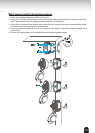
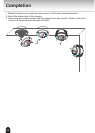
1. If you have external devices such as sensors and alarms, make the
connection from the general I/O terminal block.
2. Use the supplied RJ45 female/female
coupler to connect the Network Camera to
a switch.
Use a Category 5 Cross Cable when
Network Camera is directly connected to
PC.
3. Connect the supplied AC adapter.
N.C.
N.C.
N.C.
AC24V
AC24V
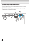
N.C.: No Connector
N.C.: No Connector
N.C.: No Connector
AC24V: Power in 24V AC
AC24V: Power in 24V AC
GND: Ground
DI : Digital Input
DO : Digital Output
+12V : 12V DC Output
GND
DI
DO
+12V
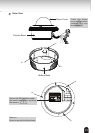
Power Input
Connect the power adapter of the supplied AC adapter, 24V AC UL Listed Class2 power supply.
The power supply of this camera is 12V DC or 24V AC
.
Connect the AC adapter jack to the Network Camera before plugging in to
the power socket. This will reduce the risk of accidental electric shock.
Be sure to use only the supplied AC adapter. Using a different AC adapter
may cause the camera to malfunction, heat up, or catch re.