© Titan Tool Inc. All rights reserved. 17
Item Part # Description Quantity
1 600-483 Tank and cover .........................................1
2 858-601 Nut ............................................................4
3 770-601 Flat washer ...............................................8
4 600-463 One-way assembly
(includes items 2, 3, and 5........................1
5 858-636 Screw ........................................................4
6 600-465 Fluid inlet assembly, PowrTex 600
DD .......1
7 600-377 Compressor screw, long ...........................2
8 600-484 Air compressor .........................................1
9 600-375 Compressor screw, short ..........................2
10 600-421 Nipple .......................................................1
11 600-372 Elbow ........................................................1
12 600-373 Compression connector............................1
13 600-374 Copper tubing ...........................................1
14 600-479 Radiator(includes item 22)........................1
15 600-371 Nipple .......................................................1
16 600-358 Street elbow..............................................1
17 600-359 Elbow ........................................................1
18 600-246 Fitting ........................................................1
19 600-370 Manifold ....................................................1
20 600-248 Elbow ........................................................1
21 600-146 Front panel ...............................................1
22 ---------- Screw ........................................................4
23 600-168 Pressure gauge ........................................1
24 600-353 Mounting nut .............................................1
25 600-178 Relief valve ...............................................1
26 600-385 Screw ........................................................1
27 600-252 Quick disconnect coupling ........................1
28 600-355 Plug ..........................................................1
29 600-136 Fluid outlet tting ......................................1
Item Part # Description Quantity
30 600-138 Bushing.....................................................1
31 600-214 Grommet ...................................................2
32 600-354 Screw ........................................................4
33 704-380 ON/OFF Switch ........................................1
34 600-218 Carriage bolt .............................................4
35 600-216 Lock nut ....................................................8
36 770-712 Carriage bolt .............................................4
37 600-485 Pump, Zip 80 ............................................1
38 600-250 Elbow ........................................................3
39 600-025 Fluid pipe ..................................................1
40 600-249 Elbow ........................................................1
41 600-095 Pressure regulator ....................................1
42 600-231 Strain relief ...............................................2
43 600-245 Plug ..........................................................1
44 600-109 Switch box ................................................1
45 704-229 Ground screw ...........................................1
46 600-486 Cart frame .................................................1
47 600-177 Lock nut ....................................................4
48 600-184 Wheel .......................................................2
49 870-004 Washer .....................................................2
50 800-019 Cap ...........................................................2
51 800-007 Axle ...........................................................1
51 600-257 Power cord (not shown)............................1
52 600-351 Air tubing, 1/4” O.D. (not shown, refer to
Air Flow Schematic — PowrTex 600
DD) ...1
53 600-346 Air tubing, 3/8” O.D. (not shown, refer to
Air Flow Schematic — PowrTex 600
DD) ...2
600-487 Cart assembly complete
(includes items 46 and 48–51))
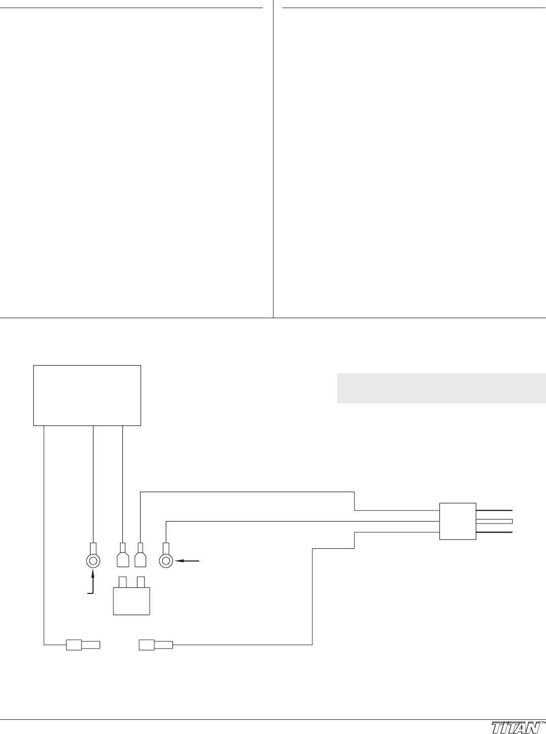
Electrical Schematic
WHITE
GREEN
GREEN
BLACK
WHITE
BLACK
Compressor
Ground screw
at switch box
Ground
screw at
switch box
ON/OFF
Switch
Power
Cord
NOTE: All electrical work should be performed
by an authorized service center.


