


[ 12 ] Pelco Manual C2914M-F (08/05)
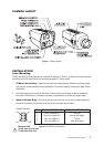
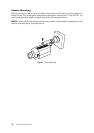
Service Connection
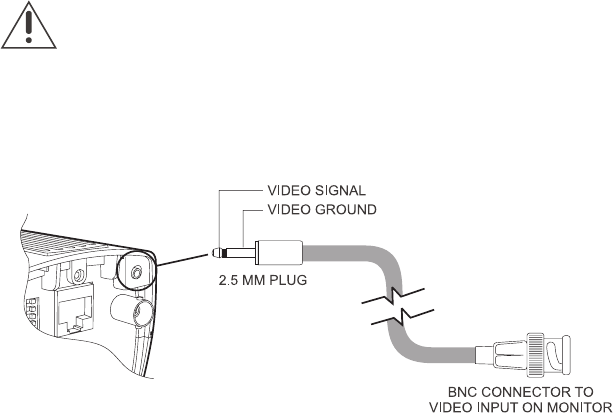
The service connector allows a video monitor to be connected locally to the camera using a 2.5 mm plug to
composite video BNC cable.
Figure 5. Service Connector
NOTE: Inserting the plug into the service connector disconnects video from the composite BNC connector on
the rear panel of the camera.
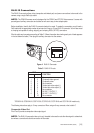
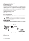
WARNING: When powering the camera via the RJ45-10 connector, ensure that the power
connections to the screw terminals on the rear of the camera are not used. The power supply must
be a UL Listed Class 2 isolated type.
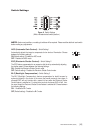
To send composite video through the RJ45-10 connector:
1. Connect composite video out to pin 3.
2. Connect composite video ground to pin 2.
Unshielded Twisted Pair (UTP)
Pins 5 and 6 allow video to be transmitted over unshielded twisted pair (UTP) wiring to equipment fitted with a
suitable receiver. Ensure that connection polarity is observed in relation to the connected twisted pair receiver.
To implement UTP, you must use 5-pair unshielded twisted cable, Cat5e, or an equivalent. The camera has a
built-in transmitter for UTP. However, you must provide a UTP receiver. Your maximum cable distance depends
on whether you install a passive or active receiver. When outputting composite video through the BNC or RJ45-
10, do not send UTP output to a passive UTP receiver. However it is acceptable to use an active UTP receiver
for UTP output in combination with the other video connections.
To send UTP video through the RJ45-10 connector:
1. Connect UTP+ video output to pin 6.
2. Connect UTP- video output to pin 5.
24 VAC/12 VDC Power Connection
Pins 8 and 9 allow connection to a power supply of 10.8 to 13.8 VDC (12 VDC -10% +15%) or 20.4 to 27.6 VAC
(24 VAC ±15%) at 50/60Hz. Correct connections and polarity must be observed.