


Pelco Manual C2914M-F (08/05) [ 9 ]
CONNECTIONS
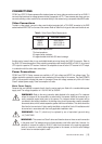
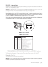
CC3610 and CC3710 Series cameras offer standard power and coax video connectors as well as an RJ45-10
connector that combines low voltage power and video (composite or UTP). These cameras also have a service
connector allowing a video monitor to be connected locally to the camera using a composite video BNC cable.
Video Connections
To obtain a video output, connect a video coaxial cable terminated with a 75 Ω BNC connector to the BNC
socket marked VIDEO OUT on the rear of the camera. Refer to Table A for the type of video coaxial cable to use.
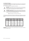
Table A. Video Coaxial Cable Requirements
Cable Type* Maximum Distance
RG59/U 750 ft (229 m)
RG6/U 1,000 ft (305 m)
RG11/U 1,500 ft (457 m)
* Minimum cable requirements:
75 ohms impedance
All-copper center conductor
All-copper braided shield with 95% braid coverage
Another way to transmit video is over unshielded twisted pair wiring through the RJ45-10 connector. Refer to
the RJ45-10 Connections section. When outputting composite video through the BNC or RJ45-10, do not send
UTP output to a passive UTP receiver. However it is acceptable to use an active UTP receiver for UTP output
in combination with the other video connections.
Power Connections
CC3610 and CC3710 Series cameras are available in AC high voltage and AC/DC low voltage types. The
voltage required to operate the camera is clearly marked on the rear panel of the camera. The green POWER
LED on the rear panel indicates that power is connected. Power low voltage cameras only from a UL Listed
Class 2 isolated power supply. Power consumption is 5 watts.
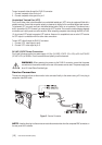
Mains Power Supply
Cameras that are intended to operate directly from the mains supply are fitted with a nondetachable power
supply cord. The voltage of operation is 110 to 240 VAC at 50/60Hz.
WARNING: Refer to the wiring instruction label attached to the supply cord. For instances
where the camera will be connected to a socket outlet, the camera should be connected to an
easily accessible socket outlet near to the camera. For instances where the camera will be
connected to the building installation, the building wiring should incorporate a readily accessible
disconnect device, with a contact separation greater than three millimeters. This device should be
fitted into the live conductor, if that is readily identifiable, or should be 2-pole. All installations shall
be carried out in accordance with the locally applicable installation rules.
WARNING: Fuse (F1) should only be replaced by one of equivalent type and rating
1A (T) HRC 250V
WARNING: This camera is a Class 2 device and therefore does not have an earth connection
in the power cord. The leakage current on these cameras is well within safe limits. However, it is
advisable to connect the coaxial or RJ45-10 cable from the camera to the receiving equipment
(such as a monitor or matrix) before applying power to the camera, so that this small leakage
current has a low resistance path to earth.