


GX3300 Technical Manual
Page 14
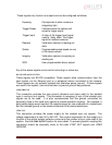
These signals only function as outputs and can be configured as follows:
Exposing Corresponds to when camera is
integrating light.
Trigger Ready Indicates when the camera will
accept a trigger signal.
Trigger Input A relay of the trigger input signal
used to “daisy chain” the trigger
signal for multiple cameras.
Readout Valid when camera is reading out
data.
Strobe Programmable pulse based on one
of the above events.
Imaging Valid when camera is exposing or
reading out.
GPO User programmable binary output.
Any of the above signals can be set for active high or active low.
RS-232 RXD and RS-232 TXD
These signals are RS-232 compatible. These signals allow communication from the
host system via the Ethernet port to a peripheral device connected to the camera.
These signals are not optically isolated and reference power ground. If these signals
are used in the system, care must be taken to prevent ground loop problems.
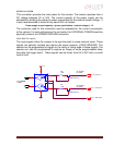
USER GROUND
This connection provides the user ground reference and return path for the isolated
sync in and sync out signals. This connection is necessary if any of the isolated sync
signals are to be used. It is also recommended that this ground connection be
physically close to the used sync signals to prevent parasitic coupling. For example, a
good cable design would connect the required signal on one conductor of a twisted pair
and the isolated ground on the second conductor of the same twisted pair.
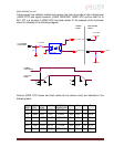
USER VCC
This connection provides the power supply for the isolated sync out signals. The
voltage requirement is from 5V to 24V DC. The current requirement for this supply is a
function of the optical isolator collector current and the number of sync outs used in the
system. See the
SYNC OUTPUT
section for more detail. To prevent parasitic coupling this
connection should be physically close to the used SYNC OUT signals and USER
GROUND.