


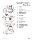
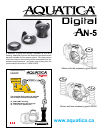

CONTROLS IN DETAIL
01. ON/OFF KNOB: Rotate to switch camera on or off
02. SHUTTER RELEASE LEVER: Press the shutter release part way to activate the camera auto focus. To release camera shutter, press all the way.
03. VIDEO ON/OFF BUTTON: Press to activate or to stop video recording.
04. PLAYBACK BUTTON: Press to activate the monitor and review images.
05. INTERNAL FLASH ACTUATING LEVER: rotate down to turn internal ash on, or to engage the internal ash mask when using external strobe
triggered by optical ber.
06. OPTICAL TYPE BULKHEAD CONNECTOR: (Show with a Sea & Sea type of sync cord adapter). To connect Sea & Sea type optical ber cord.
07. OPTICAL TYPE BULKHEAD CONNECTOR: (Show with an INON type of sync cord adapter).To connect INON and other type of straight type
optical ber cord.
08. MOUNTING HOLE FOR ACCESSORY: a 1/4”-20 TPI hole is supplied to accept a TLC accessory or TLC base ball for mounting a strobe arm or
a modeling light.
09. FLASH BLOCKING MASK: This mask is used when external strobe are used, it blocks off stray light from the internal ash to prevent lighting up
suspended particles in front of the camera.
10. FOCUS/ZOOM KNOB: Turning allows manual focus of a single focus lens or rotation of the zoom mechanism of a zoom lens.
11. FOCUS/ZOOM PINION GEAR: Engages and operates the focus or zoom gear attached to the lens. A release lever (key # 18) is provided to
disengage the knob when removing the camera from the housing with the lens attached.
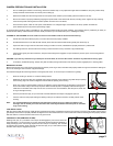
12. LATCH: This heavy duty latch is equipped with a safety lock to protect against accidental opening.
13. SAFETY CATCH TAB: This tab secures the main latch against accidental opening.
14. BAYONNET MOUNTING FLANGE: allows the mounting of different ports and extension rings on the housing.
15. REMOVABLE CAMERA TRAY: Used to attach camera and slide in housing.
16. CAMERA MOUNTING SCREWS: this 1/4-20 screw is for attaching the camera to the removable tray.
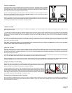
17. PORT RELEASE LEVER: Rotate clockwise to disengage the port lock, Press down and rotate counter clockwise to reengage the locking
mechanism when installing or removing a port or extension.
18. HAND STRAP LUGS: Two lugs are provided for the hand strap.
19. HAND STRAP LUGS: An adjustable hand strap is provided for securely handling the housing underwater.
20. MENU BUTTON: Press to activate menu display, scroll using control wheel (key #18) and select using enter button (key # 19).
21. CONTROL WHEEL: Rotate to scroll through the camera functions and menus, press the enter button (key 19) to conrm choice.
22. ENTER BUTTON: Press to acknowledge selected function or for accessing the shooting mode.
23. SHOOTING TIPS BUTTON: Press to display shooting tips function
24. MONITOR DISPLAY WINDOW: allow viewing of menus, information and images
25. MOISTURE ALARM LED RECEPTACLE: To accept the warning ashing LED of the optional moisture alarm.
26. ACCESSORY GRIP MOUNTING HOLES: Four threaded holes are ready to accept accessory grips.
27. TOP MOUNTING HOLES: a 1/4” X 20 hole is provided for mounting a strobes arm, focus light or accessories.
28. BOTTOM MOUNTING HOLES: a 1/4” X 20 hole is provided for mounting strobes trays or accessories.
29. RUBBER ANTI SKID PADS: three rubber pads are provided to protect the housing and preventing it from sliding on wet decks.
30. SACRIFICIAL ANODES: A zinc anode is provided to protect your housing against salt water corrosion; it is designed to deteriorate faster than
the other strategic metal of your housing, hence the name sacricial anodes. This anodes need to be replaced periodically by the user as needed.
31. MOUTING HOLES FOR OPTIONAL GRIPS: Two mounting points are incorporated in the housing design; grips can be mounted on each side
of the housing.
32. OPTIONAL MOISTURE ALARM: Two mounting holes are provided for mounting an optional moisture alarm in the housing.
page 3