


M
M
a
a
k
k
i
i
n
n
g
g
t
t
h
h
e
e
C
C
o
o
n
n
n
n
e
e
c
c
t
t
i
i
o
o
n
n
s
s
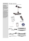
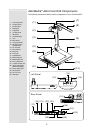
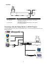
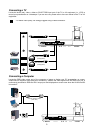
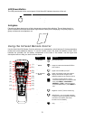
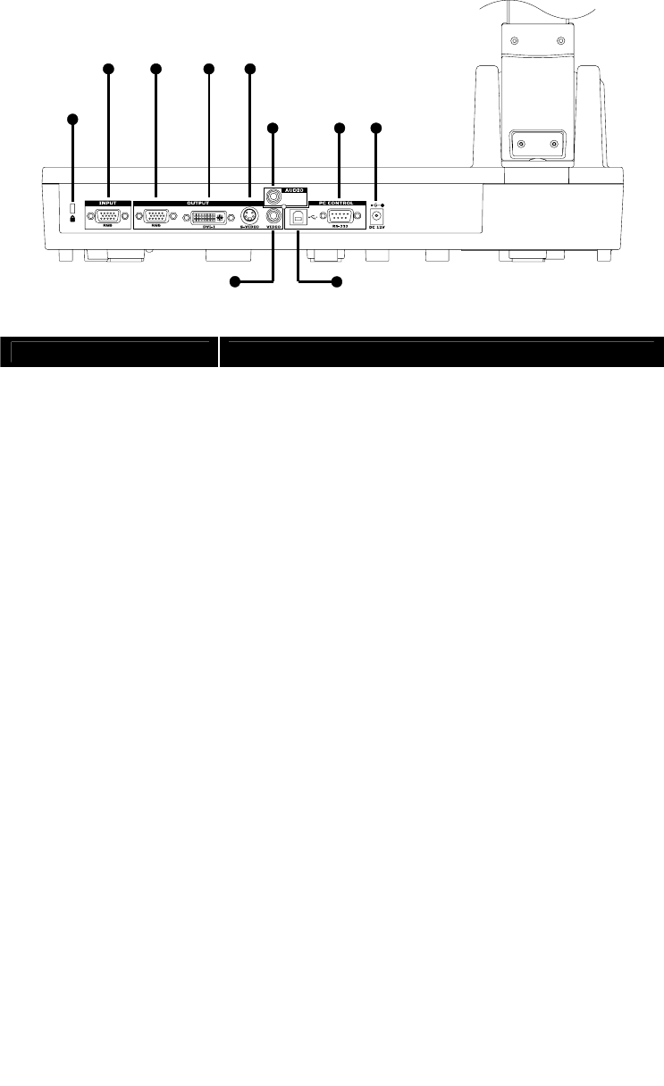
The ports at the back and left panel of the AVerVision530 enable you to connect the unit to a computer,
graphics display monitor, LCD/DLP projector, TV or other devices. Illustrated below are the ports located at
the back and left panel of the AVerVision530 with their corresponding labels.
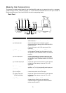
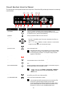
Back Panel
(1)
(2) (3) (4) (5)
(6) (7) (8)
(9) (10)
Name Function
(1) Antitheft slot : Attach a Kensington compatible security lock or
antitheft device.
(2) RGB input port : Input RGB signal from a computer or other
sources and pass it through to the RGB and DVI-I
output port only.
Connect this port to the VGA output port of the
computer.
(3) RGB output port : Output RGB signal from camera, RGB input port,
or the captured images from the memory source
and preview it on a VGA/Mac monitor or LCD/DLP
projector.
(4) DVI-I output port Output RGB signal from camera, RGB input port,
or the captured images from the memory source
and preview it on a VGA/Mac monitor or LCD/DLP
projector.
(5) S-Video output port : Output the signal from the camera or the captured
images from the memory source on TV or AV
equipment.
(6) Audio output port : Output the microphone audio signal to an
amplifier, on TV or AV equipment audio input port.
(7) RS-232 port : Control AVerVision530 using a PC.
(8) DC 12V port : Connect the power cord into this port.
(9) Video output port
(RCA/Composite)
:
Output the signal from the camera or the captured
images from the memory source on TV or AV
equipment.
(10) USB port : Use AVerVision530 as a PC Camera or Mass
storage device allowing you to transfer the
captured images to and from the AVerVision530
memory source and PC.
3