


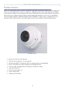
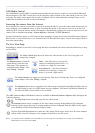
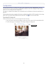

AXIS 212 PTZ - Product Features
7
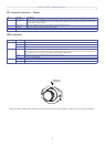
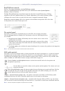
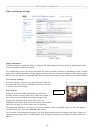
I/O terminal connector - Pinout
4 Transistor Out-
put
With a maximum load of 50mA and a maximum voltage of 24V DC, this output has an open-collector NPN transistor with the
emitter connected to the GND pin. If used with an external relay, a diode must be connected in parallel with the load, for pro
-
tection against voltage transients.
3 Digital Input Connect to GND to activate, or leave floating (or unconnected) to deactivate.
2 3.3V DC Can be used to power auxiliary equipment, max 50mA.
1 GND
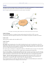
LED indicators
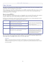
Network Green Steady for connection to 100 Mbit/s network. Flashes for network activity.
Amber Steady for connection to 10 Mbit/s network. Flashes for network activity.
Unlit No connection.
Status Green Shows steady green for normal operation.
Note: The Status LED can be configured to be unlit during normal operation, or to flash only when the camera is accessed. See the
online help files for more information. Go to Setup > System Options > LED settings
Amber Steady during startup, reset to factory default or when restoring settings.
Red Slow flash for failed upgrade.
Power Green Normal operation.
Amber Flashes green/amber during firmware upgrade.
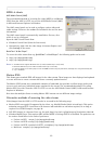
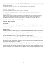
Network
connector
up
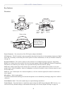
Note: The AXIS 212 PTZ must be mounted with the network connector facing upwards to achieve the correct image orientation.
Pin Function Description
LED Color Description