


Page 14 AXIS 225FD Installation Guide
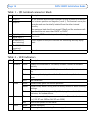
Table 1 - I/O terminal connector block
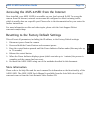
Table 2 - LED indicators
Pin Function Description
1 Output A On the external device output terminals (A and B), there is no distinc-
tion between positive and negative (+ and -). The terminals use a pho-
tocoupler and are electrically isolated from the other internal
cir
cuitry.
The maximum load should not exceed 100mA and the maximum volt-
age should be not more than 50VDC or 35VAC.
2 Output B
3 Digital Input 1 Connect to GND to activate, or leave floating (or unconnected) to
deactivate.
4 Digital Input 2
5 RS-485/422-A
(non-inverting)
A half-duplex RS-485/422 interface for controlling auxiliary equip-
ment.
6 RS-485/422-B
(inverting)
7 GND Ground.
LED Function Color Description
1 Network Green Steady for connection to 100 Mbit/s network.
Flashes for network
activity.
Amber Steady for connection to 10 Mbit/s network. Flashes for network activ-
ity.
Red Flashes rapid red, together with the Status indicator, for hardware
erro
r.
Unlit No connection.
2 Status Green Shows steady green for normal operation.
Amber Shows steady amber during reset to fact
ory default or when restoring
settings.
Red Slow flash for failed upgrade. Rapid flash
, together with the Network
indicator, for hardware error.
3 Heater Green Steady green when the power connected is sufficient for the heater
i.e. (12V DC min 20W or 24V AC min 25VA)
Red Insufficient power for the heater.
4 Power Green Normal operation.
Amber Flashes green/amber during firmware upgrade.