


AXIS 225FD Installation Guide Page 5
ENGLISH
DEUTSCH
ESPAÑOL
ITALIANO
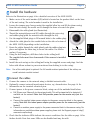
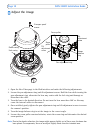
Install the hardware
Refer to the illustration on page 4 for a detailed overview of the AXIS 225FD.
1. Make a note of the serial number (S/N) which is located on the product label on the base
of the unit casing.
The serial number is used in the installation.
2. Loosen the tamper-proof screws using the supplied allen key and lift the dome casing
fro
m the unit casing. Be careful not to damage the dome or scratch the glass.
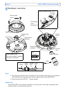
3. Disassemble the cable gland (see illustration).
4. Thread the network/power and I/O cables through the outer ring
and
rubber plug (push the network cable through the slit).
5. Use the supplied blind plugs to fill unused holes in the rubber plug.
6. Attach the cable gland to the condui
t hole on the side or bottom of
the AXIS 225FD, depending on the installation.
7. Route the cables through the cable gland, push the rubber plug into
pl
ace and tighten the outer ring to secure the cables. Use silicon
sealant, if necessary.
8. Using the drill template, drill th
ree holes in the ceiling/wall.
The conduit hole must face downwards if the camera is installed
vertically.
9. Install the unit casing on the ceiling/wall u
sing the supplied screws and plugs. Seal the
holes with silicon sealant to prevent moisture from leaking in to the casing.
Note: Use of the cable gland is optional. For full vandal resistant protection of the cables, u
se
vandal resistant conduits instead.
Connect the cables
1. Connect the camera to the network using a shielded network cable.
2. Optionally connect external input/output devices, e.g. alarm devices. See page 14 for
information on the termi
nal connector pins.
3. Connect power to the power connector block,
using one of the methods listed below:
• PoE (Power over Ethernet) via the network cable. This will automat
ically be detected if
available via the network. Note that PoE provides power for the camera only (not the
heater).
• Connect the supplied indoor power adapter to t
he power connector block in the camera
casing. Note that this indoor power adapter provides power for the camera only (not the
heater).
• Connect an outdoor power supply to the power connector block in the camera casing. For
information on available outdoor power supplies, please visit the Support pages at http://
www.axis.com/techsup/
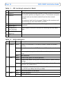
4. Check that the indicator LEDs indicate th
e correct conditions. See the table on page 14 for
further details. Note that some LEDs can be disabled and may be unlit.
Conduit hole
must face
downwards