


AXIS M3114-R Network Camera
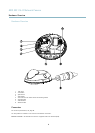
Hardware Overview
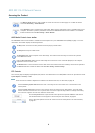
Network connector - D-coded M12 connector. Supports Power over Ethernet (PoE).
NOTICENOTICE
NOTICE
The product shall be connected using a shielded network cable (STP). All cables connecting the product to the network
switch shall be shielded (STP) and intended for their specic use. Make sure that the network switch is properly grounded.
See for regulatory requirements.
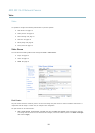
Control button - The control button is used for:
• Connecting to an AXIS Video Hosting System service. See page 35. To connect, press and hold the button for
about 1 second until the Status LED ashes green.
• Connecting to AXIS Internet Dynamic DNS Service. See page 36. To connect, press and hold the button for
about 3 seconds.
• Resetting the product to factory default settings. See page 41.
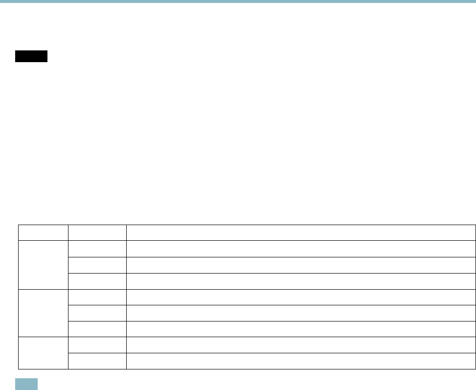
LED Indicators
LED
Color
Indication
Green
Steady for connection to a 100 MBit/s network. Flashes for network activity.
Amber
Steady for connection to a 10 MBit/s network. Flashes for network activity.
Network
Unlit No network connection.
Green Steady green for normal operation.
Amber
Steady during startup and when restoring settings.
Status
Red
Slow ash for failed upgrade.
Green
Normal operation.Power
Amber
Flashes green/amber during rmware upgrade.
Note
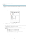
• The Status LED can be congured to be unlit during normal operation. To congure, go to Setup > System Options > Ports
& Devices > LED. See the online help for more information.
• The Status LED can be congured to ash while an event is active.
• The Status LED can be congured to ash for identifying the unit. Go to Setup > System Options > Maintenance .
5