


AXIS P1346 Network Camera
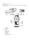
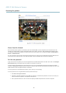
Hardware overview
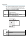
Connectors
Network connector - RJ-45 Ethernet connector. Supports P ower over Ethernet (PoE).
Caution
Due to local regulations or the environmental and elec trical conditions in which the product is to be used, a shielde d
network cable (STP) may be appropriate or req uired. Any network c ables that are routed in outdoor environments or similar
shall be shielded (STP) and intended for their specific use. Make sure that the network switch is properly grounded. See
Electromagnetic Compatibility (EMC) for regulatory requirements.
Audio in (pink) - 3.5 mm input for a mono microphone, or a line-in mono signal (left channel is used from a stereo signal).
Audio out (green) - 3.5 mm output for audio (line level) that can be connected to a public address (PA) system or a n active speaker
with a built-in a mplifier. A stereo connector must be used for the audio out.
SD card slot - A standard or high-capacity SD card (not included) can be used for local recording with removable storage. For
instructions on how to insert and remove an SD card, please refer to the Installation Guide.
Note
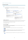
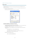
Before removal, the SD card should be unmounted to prevent corruption of recordings. To unmount the SD card, go to Setup
>SystemOptions>Storage>SDCardand click Unmount.
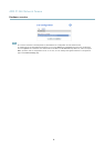
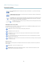
Control button - The control button is used for:
• Enabling the Focus A ssistant. Press and very quickly release the C ontrol button.
• ConnectingtoanAXISVideoHostingSystemservice.Seepage 44. To connect, press and hold the button for about
1 second until the Status LED flashes green.
• ConnectingtoAXISInternetDynamicDNSService.Seepage 44. To connect, press and hold the button for
about 3 seconds.
• Resetting the product to factory default settings. See page 50.
Power connector - 2-pin terminal block for power input.
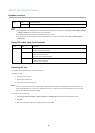
I/O connector
DC power input
Note
For technical specifications, see pag e 56.
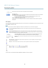
I/O terminal connector - Use in applications for e.g. motion detection, event triggering, time lapse recording and alarm notifications.
In addition to an auxiliary power and a GND pin, the I/O terminal connector provides the interface to:
6