


AXIS P1346–E Network Camera
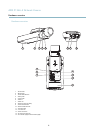
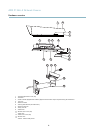
Hardware overview
Note
For technical specifications, see page 57.
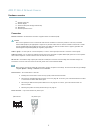
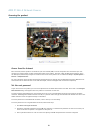
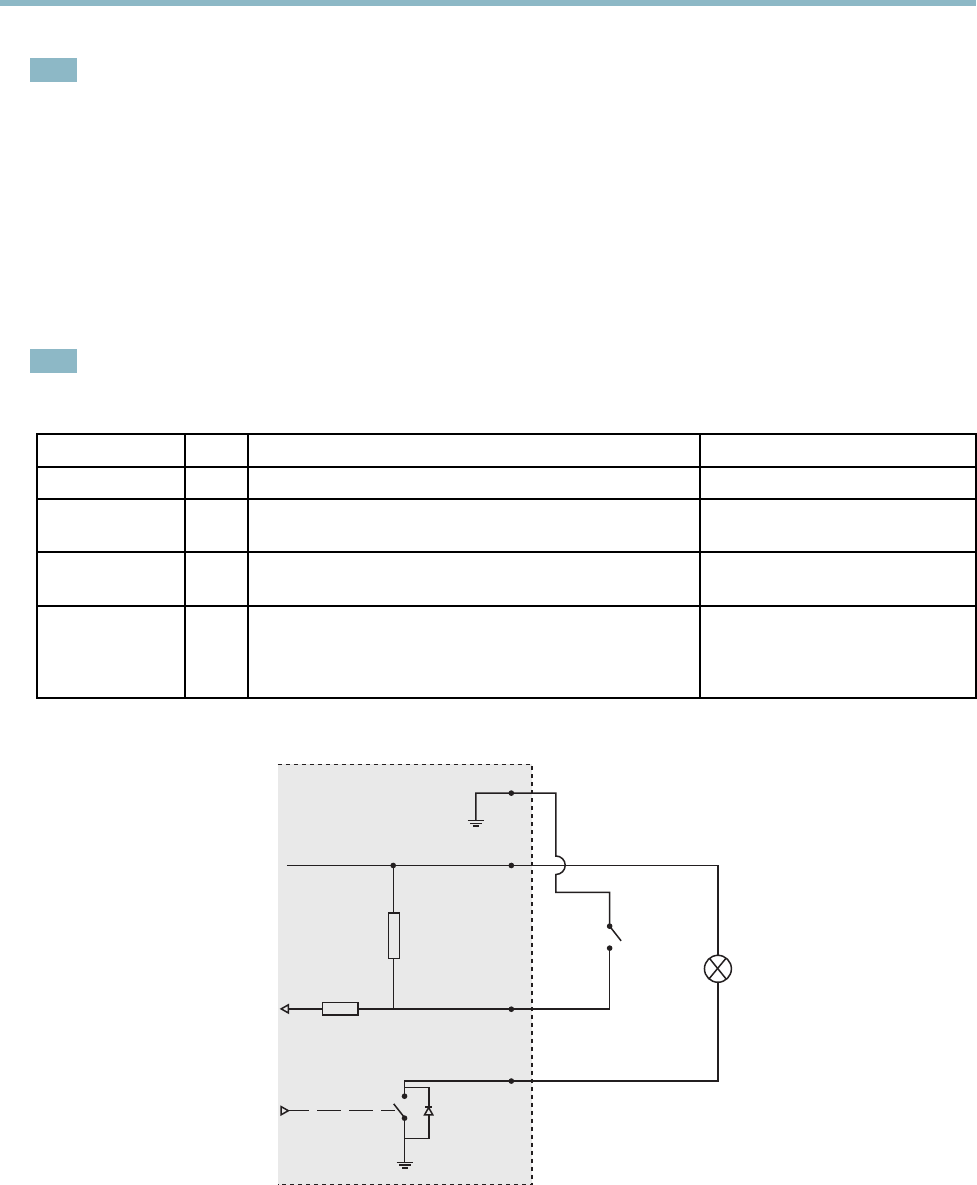
I/O terminal connector - Use in applications for e.g. m otion detection, event triggering, time lapse recording and alarm notifications.
In addition to an auxili ary power and a GND pin, the I/O terminal connector provides the interface to:
• Digital output — For connecting external devices such as relays and LEDs. Connected devices can be activated by
the VAPIX® Application Programming Interface, output b u ttons on the Live View page or by an Action Rule. The
output will show as active (shown under System Options > Ports & Devices) if the alarm device is activated.
• Digital input — An alarm input for connecting devices tha t can toggle between an open and closed circuit, for
example: PIRs, door/window contacts, glass break detectors, etc. When a signal is received the state changes and
the input becomes a ctive (shown under System Options > Ports & Devices).
Note
The I/O connector is connected to the housing (fan/heater) on delivery, and will trigger an input port event to indicate a fan
or heater error when activated. See Events, on page 36 for information on how to set up an event.
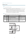
Function Pin Notes
Specifications
GND
1
Ground
3.3 V DC Power
2
Can be used to power auxiliary equip ment.
Note: This pin can only be used as power out.
Max load = 50 mA
Digital Input
3
Connect to GND to activate, or leave floating (unconnected)
to deactivate.
0to+40VDC
Digital Output
4
Internal connection to ground when activated, floating
(unconnected) when deactivated. If used with an inductive
load, e.g. a relay, a diode must be connected in parallel with
the load, for protection against voltag e trans ients .
Max load =100 mA
Max voltage = +40 V DC
3.3 V max 50 mA
1
2
3
4
8