


AXIS Q1635 Fixed Network Camera
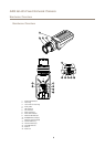
Hardware Overview
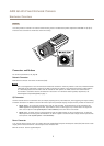
Audio Connector
The Axis product has the following audio connectors:
• Audio in (pink) – 3.5 mm input for a mono microphone, or a line-in mono signal.
• Audio out (green) – 3.5 mm output for audio (line level) that can be connected to a public address (PA) system or an
active speaker with a built-in amplier. A stereo connector must be used for audio out.
RS485/RS422 Connector
Two terminal blocks for RS485/RS422 serial interface used to control auxiliary equipment such as PTZ devices.
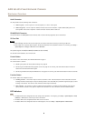
SD Card Slot
NONO
NO
TICETICE
TICE
• Risk of damage to SD card. Do not use sharp tools or excessive force when inserting or removing the SD card.
• Risk of data loss. To prevent data corruption, the SD card should be unmounted before removal. To unmount, go to Setup >
System Options > Storage > SD Card and click Unmount.
This product supports microSD/microSDHC/microSDXC card (not included).
For SD card recommendations, see www.axis.com
Control Button
For location of the control button, see Hardware Overview on page 6 .
The control button is used for:
• Resetting the product to factory default settings. See page 61.
• Connecting to an AXIS Video Hosting System service. See page 53. To connect, press and hold the button for about 3
seconds until the Status LED ashes green.
• Connecting to AXIS Internet Dynamic DNS Service. See page 53. To connect, press and hold the button for about 3 seconds.
Function Button
The function button has multiple functions:
• Levelling assistant – This function helps to ensure the camera is level. Press the button for about 3 seconds to start the
levelling assistant and press again to stop the leveling assistant. The status LED (see ) and buzzer signal (see page 9 ) assist
levelling of the camera. The camera is level when the buzzer beeps continuously.
• Focus assistant – This function is used for enabling the Focus Assistant. To enable the focus assistant, press and very
quickly release the button. Press again to stop the focus assistant. For more information, see the Installation Guide.
LED Indicators
Note
• The Status LED can be congured to be unlit during normal operation. To congure, go to Setup > System Options > Ports
& Devices > LED. See the online help for more information.
• The Status LED can be congured to ash while an event is active.
• The Status LED can be congured to ash for identifying the unit. Go to Setup > System Options > Maintenance .
8