


AXIS Q1635 Network Camera
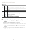
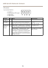
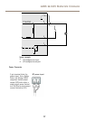
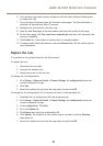
I/O connector
4–pin terminal block for:
• 0 V DC (-)
• Auxiliary power (DC output)
• Digital Input
• Digital Output
1
2 3 4
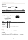
Function Pin Notes
Specications
0 V DC (-)
1
DC output
2
Can be used to power auxiliary equipment.
Note: This pin can only be used as power out.
12 V DC
Max load = 50 mA
Digital input – Connect to pin 1 to activate,
or leave oating (unconnected) to deactivate.
0 to max 30 V DCCongurable
(Input or
Output)
3–
4
Digital output – Connected to pin 1 when
activated, oating (unconnected) when
deactivated. If used with an inductive load,
e.g. a relay, a diode must be connected in
parallel with the load, for protection against
voltage transients.
0 to max 30 V DC, open
drain, 100 mA
16