


AXIS Q6044-C PTZ Dome Network Camera
Multi-Connector Cable
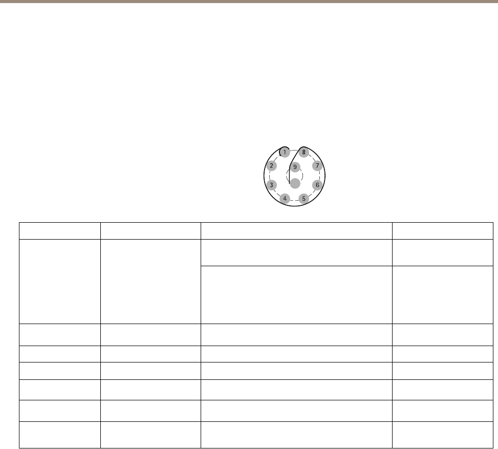
Multi-Connector Cable
The supplied multi-connector cable is required in order to maintain the camera’s IP rating.
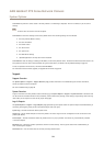
The multi-connector cable is connected to the camera’s multi-connector, see Hardware Overview on page 6 .
The wires are connected to the supplied media converter switch, see Media Converter Switch on page 8 .
The cable provides the following signals:
• DC power to camera
• Network (Ethernet 10/100Base-T)
• Input/Output (I/O)
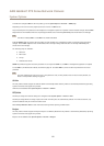
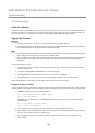
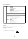
1 8
2 7
9
3 6
4 5
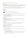
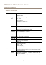
Function Pin – wire Notes
Specications
Digital input – Connect to pin 8 to activate, or
leave oating (unconnected) to deactivate.
0 to max 30 V DC
Congurable (Input
or Output)
2 – blue
7 – yellow
Digital output – Connected to pin 1 when
activated, oating (unconnected) when
deactivated. If used with an inductive load, e.g. a
relay, a diode must be connected in parallel with
the load, for protection against voltage transients.
0 to max 30 V DC, open
drain, 100 mA
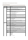
RX+
3 – green/white
Ethernet – receiving
RX-
4 – green
Ethernet – receiving
TX+
5 – orange/white
Ethernet – transmitting
TX-
6 – orange
Ethernet – transmitting
0 V DC (-)
8 – black
0 V DC
DC output (12 V)
1, 9 – red Used to power camera
12–13.2 V DC
Max load = 6 A
57