


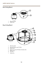
AXIS Q604 Series
Multi-Connector Cable (sold separately)
When connecting external equipment to the Axis product, a multi-connector cable (available from
Axis) is required in order to maintain the product’s IP rating. The multi-connector cable can be
purchased from your Axis reseller.
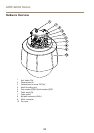
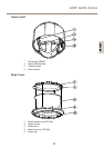
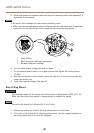
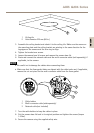
Connect the multi-connector cable to the product’s multi-connector. To locate the multi-connector,
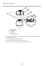
see Hardware Overview on page 10. The cable provides the following connectors:
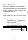
Power connector - 3-pin terminal block used for power input. See image below. Use a Safety Extra
Low Voltage (SELV) compliant limited power source (LPS) with either a rated output power limited
to ≤100 W or a rated output current limited to ≤5 A.
Audio in (pink) - 3.5 mm input for a mono microphone, or a line-in mono signal (left channel is
used from a stereo signal).
Audio out (green) - 3.5 mm output for audio (line level) that can be connected to a public address
(PA) system or an active speaker with a built-in amplier. A stereo connector must be used for the
audio out.
I/O terminal connector - Use with external devices in combination with, for example, tampering
alarms, motion detection, event triggering, time lapse recording and alarm notications. In addition
to the 0 V DC reference point and power (DC output), the I/O connector provides the interface to:
• Digital output — For connecting external devices such as relays and LEDs.
Connected devices can be activated by the VAPIX® Application Programming
Interface, output buttons on the Live View page or by an Action Rule. The output
will show as active (shown under System Options > Port & Devices > Port
Status) if the alarm device is activated.
• Digital input — An alarm input for connecting devices that can toggle between
an open and closed circuit, for example: PIRs, door/window contacts, glass
break detectors, etc. When a signal is received the state changes and the input
becomes active (shown under System Options > Port & Devices > Port Status).
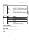
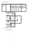
Function Pin Notes
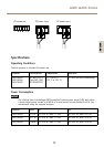
Specications
0 V DC (-)
1
DC output
2
Can be used to power auxiliary equipment.
Note: This pin can only be used as power
out.
3.3 V DC
Max load =
250 mA
15
ENGLISH