


AXIS Q6045-C PTZ Dome Network Camera
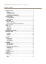
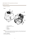
Hardware Overview
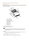
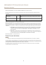
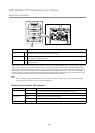
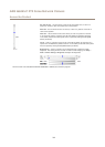
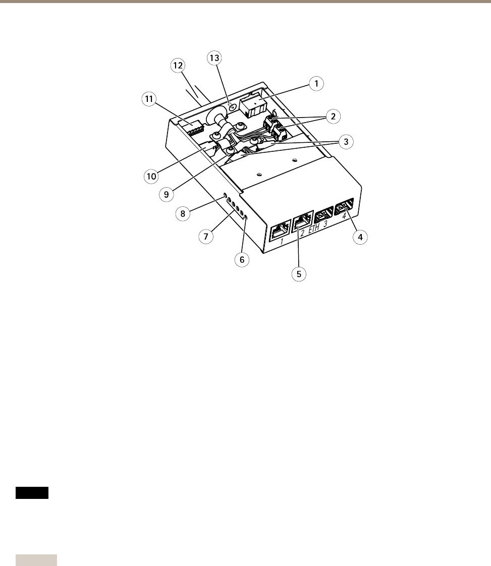
Media Converter Switch
1
2
3
4
5
6
7
8
10
9
11
12
13
1
Power connector (DC input)
2
Power connector (DC output)
3
Network connector (internal)
4
Network slot SFP (external) (2x)
5
Network connector RJ45 (external) (2x)
6
Camera LED indicator
7
Network LED indicator (4x)
8
Power LED indicator
9
Ground clip
10
I/O connector (internal)
11
I/O connector (external)
12
Multi-connector cable
13
Ground screw
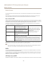
Media Converter Switch Connectors
For technical specications, see page 62.
NONO
NO
TICETICE
TICE
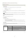
The product shall be connected using a shielded network cable (STP) or an optical ber cable. All cables connecting the
product to the network shall be intended for their specic use. Make sure that the network devices are installed in
accordance with the manufacturer’s instructions. For information about regulatory requirements, see Electromagnetic
Compatibility (EMC) on page 2 .
Important
The media converter switch does not support hotswapping. Disconnect power from the switch before swapping cameras. An
attempt to hotswap could cause the switch to freeze, in which case it must be restarted.
Power connector (DC input) - 2-pin terminal block for power input.
Power connector (DC output) - Two 2-pin terminal block for power output (pin 4 is not used).
Network connector RJ45 (external) - Two RJ45 connectors (10/100Base-T) for network connectivity.
8