


AXIS Q7424–R Mk II Video Encoder
Technical Specifications
Function/group
Item
Specications
Video
management
software
AXIS Camera Companion, AXIS Camera Station, Video management software from Axis’
Application Development Partners available on www.axis.com/techsup/software
Optional
accessories
AXIS T8310 Video Surveillance Control Board
AXIS T8006A PS12 Power Supply
AXIS T8604 Media Converter Switch
AXIS T91A03 DIN Rail Clip
Warranty
Axis 3-year warranty and AXIS Extended Warranty option, see www.axis.com/warranty
1. This product includes software developed by the OpenSSL Project for use in the OpenSSL Toolkit. (www.openssl.org), and cryptographic
software written by Eric Young (eay@cryptsoft.com).
Connectors
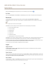
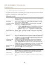
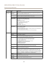
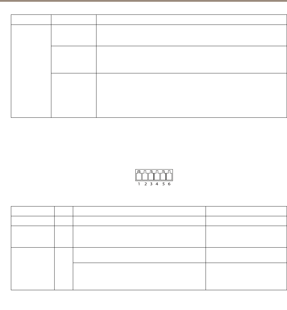
I/O Connector
6–pin terminal block
1 2 3 4 5 6
For an example diagram, see Connection Diagrams on page 65.
Function Pin Notes
Specications
0 V DC (-)
1
0 V DC
DC output
2
Can be used to power auxiliary equipment.
Note: This pin can only be used as power out.
12 V DC
Max load = 125 mA
Digital input – Connect to pin 1 to activate, or leave oating
(unconnected) to deactivate.
0 to max 30 V DCCongurable
(Input or Output)
3–6
Digital output – Connected to pin 1 when activated, oating
(unconnected) when deactivated. If used with an inductive
load, e.g. a relay, a diode must be connected in parallel with
the load, for protection against voltage transients.
0 to max 30 V DC, open drain,
100 mA
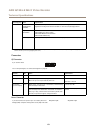
Power Connector
3-pin terminal block for power input. Use a Safety Extra Low
Voltage (SELV) compliant limited power source (LPS) with either
DC power input AC power input
63