


12 en | Installation Corner-mount No-grip Camera
F.01U.172.707 | 3.0 | 2011.02 Instruction Manual Bosch Security Systems, Inc.
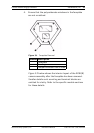
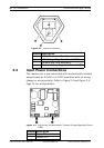
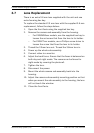
Figure 3.2 Layout of Modules
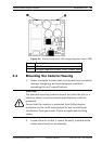
3.3 Input Power Connections
The camera unit is pre-connected with an electrically isolated
power board for 24 VAC or 12 VDC operation with no wiring
change or wiring polarity. Refer to Figure 3.3 and Figure 3.4,
Page 13, for wiring details.
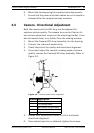
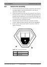
Figure 3.3 Electrically Isolated Board, Camera Voltage Regulator Board
(VRB)
Number Description
1 LED / Illuminator Board
2 LED Voltage Regulator Board (VRB)
3 Camera and Lens assembly
4 Camera Voltage Regulator Board (VRB)
Number Description
1Power IN
2Power OUT