


Dinion
XF
| Installation Manual
Bosch Security Systems | 2004-01 | V1.0
EN | 24
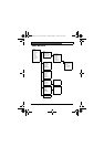
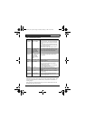
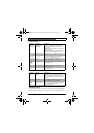
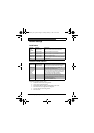
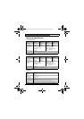
Install I/O --> Alarm submenu
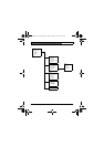
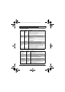
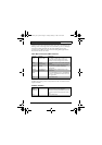
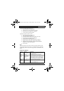
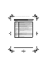
Install sync submenu
Note
VPHASE, HPHASE and SUB-PHASE cannot be accessed if there is no
valid locking signal.
Function Selection Description
ACTIVE NONE, HIGH,
LOW
Selects active_HIGH or active_LOW for the alarm
input connector. Select NONE to disable alarm
switching.
ACTION NONE, MONO,
MODE1, MODE2,
MODE3
Selects the operating mode of the camera upon
switching the alarm input.
ALARM
OUT
VMD, REMOTE,
DAY/NIGHT,
FILTER MOVE
•Select VMD to close the output relay upon VMD
alarms.
•Select REMOTE to make the output relay available
to remote communication devices.
•Day/night: the alarm output relay closes if the
camera operates in monochrome mode.
•Filter move: the alarm output relay closes before the
filter starts moving (in either direction) and opens
when the video level has stabilized (2 - 3 seconds).
EXIT Return to the I/O menu
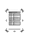
Function Selection Description
SYNC INTERNAL, LINE
LOCK, HV
LOCK,
GENLOCK
Select INTERNAL for free running camera operation,
select LINE LOCK to lock to the power supply
frequency, select HV LOCK to lock to the signal
supplied to the external sync input, select
GENLOCK to lock the subcarrier as well.
DETECTED
SYNC
Shows the actual sync mode used by the camera.
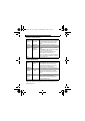
VPHASE 0, 2, … 358 Adjusts the vertical phase offset (when in LINE
LOCK mode and a valid power supply frequency is
detected).
HPHASE -25, …, 0, …
+125
Adjust the horizontal phase offset (when in EXT lock
mode and a valid input signal is detected)
SUB
PHASE
0, 2, … 358 Adjusts the sub-carrier phase offset (when in EXT
LOCK mode and a valid sub-carrier is detected).
EXIT Return to the INSTALL menu
DinionXFD_Nv1_0.book Page 24 Friday, January 7, 2005 10:56 AM