


100 en | Configuring the IP AutoDome VG4 Modular Camera System
F.01U.133.268 | 6.0 | 2010.03 User’s Manual Bosch Security Systems, Inc.
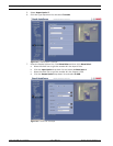
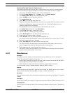
Recording status
The graphic indicates the recording activity of the IP AutoDome. You will see an animated
graphic while recording is taking place.
10.43 Advanced Mode: Recording Status
Certain details on the recording status are displayed here for information purposes. You
cannot change any of these settings.
10.44 Advanced Mode: Alarm Connections
You can select how the IP AutoDome responds to an alarm. In the event of an alarm, the unit
can automatically connect to a pre-defined IP address. You can enter up to ten IP addresses to
which the IP AutoDome will connect in sequence in the event of an alarm, until a connection is
made.
Connect on alarm
Select On so that the IP AutoDome automatically connects to a predefined IP address in the
event of an alarm.
By setting Follows input 1 the unit maintains the connection that has been automatically
established for as long as an alarm exists on alarm input 1.
Number of destination IP address
Specify the numbers of the IP addresses to be contacted in the event of an alarm. The unit
contacts the remote stations one after the other in the numbered sequence until a connection
is made.
Destination IP address
For each number, enter the corresponding IP address for the desired remote station.
Destination password
If the remote station is password protected, enter the password here.
In this page, you can save a maximum of ten destination IP addresses and hence up to ten
passwords for connecting to remote stations. If connections to more than ten remote stations
are to be possible, for example when initiating connections via higher-ranking systems such as
VIDOS or Bosch Video Management System, you can store a general password here. The IP
AutoDome can use this general password to connect to all remote stations protected with the
same password. In this case, proceed as follows:
1. Select 10 from the Number of destination IP address list field.
2. Enter the address 0.0.0.0 in the Destination IP address field.
3. Enter your chosen password in the Destination password field.
4. Define this password as the user password for all remote stations to which a connection
is to be possible.
NOTICE!
In the default setting, Stream 2 is transmitted for alarm connections. Bear this fact in mind
when assigning the profile (see Section 10.16 Advanced Mode: Encoder Profile, page 78).
NOTICE!
If you enter the destination IP address 0.0.0.0 for destination 10, this address will no longer
be used for the tenth attempt at automatic connection in the event of an alarm. The parameter
is then used only to save the general password.