


4 en | Camera Setup AutoDome 100 Series Fixed Camera
F.01U.216.346 | 1.0 | 2011.04 User Manual Bosch Security Systems, Inc.
1 Camera Setup
Install and wire the 100 Series AutoDome according to the VG5 AutoDome Installation Manual.
A typical system includes a keyboard, matrix switcher, monitor, and appropriate wiring
connections. Please refer to the individual product manuals for complete installation and
setup instructions for each of the system components.
1.1 Configuring the Camera
To assist setup, the VG5-100 Series camera module can be connected to a monitor through
the miniature 2.5 mm monitor jack located on the camera circuit board. The monitor jack
provides a composite video signal with synchronization. An optional cable (part number
S1460) is available for making this connection.
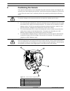
To access the monitor jack, remove the bubble and covert liner:
1. Insert a small screw driver through the keyway in the Pendant trim-ring, rotate the dome
bubble counterclockwise and remove the dome bubble. For In-Ceiling AutoDomes, you
must loosen the small screw in the trim ring before rotating the bubble.
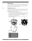
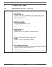
2. Press and hold the two retention buttons on each side of the camera module and then
pull off the covert liner. See the image below.
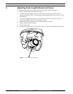
Removing the covert liner provides access to the menu keys, and the pan and tilt
thumbscrew adjustment locks.
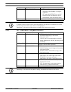
Figure 1.1 100 Series Camera Module
Ref Description
1Front View
2 Back View
3 Retention Button (2)
4Covert Liner
5Menu Keyboard
6 Monitor Jack