


2-6
Cisco Video Surveillance 6030 IP Camera Installation Guide
OL-28492-02
Chapter 2 Camera Installation
Installing the IP Camera with a Vandal Resistant Enclosure
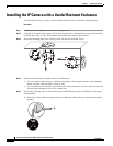
Step 6 (Optional) Perform the following steps to install and connect an external power cable and I/O cables for
external devices:
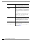
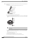
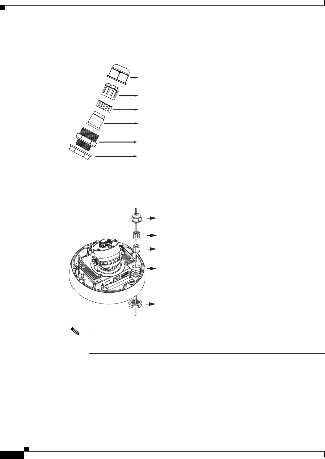
a. Disassemble the components of the waterproof connector into parts (A) ~ (F).
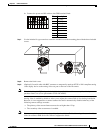
b. Place the screw nut (E) on the power and I/O cable opening.
c. Feed the power cable through the waterproof connector (F --> E --> D --> B --> A). Be sure to feed
enough power cable length through the waterproof connector to connect the power cable to the GPIO
block.
Note There are 8 holes on the seal (D), and the widest holes with a crack on the side are specific
for power cables.
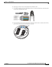
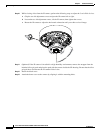
d. Feed the I/O cables through the waterproof connector (F --> E --> D --> B --> A). Be sure to feed
enough I/O cable length through the waterproof connector to connect the I/O cable to the GPIO
block.
The recommended cable gauge is 2.0 ~ 2.8 mm.
e. Push the seal (D) into the housing (B).
f. Insert the seals (C) into unused holes on the seal (D) to avoid moisture.
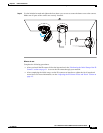
g. Secure the sealing nut (A) tightly and hex nut (F) from the bottom of the camera.
Sealing Nut (A)
Housing (B)
Seals (C)
Seal (D)
Screw Nut (E)
Hex Nut (F)
(A)
(D)
(B)
(F)
(E)