


2-7
Cisco Video Surveillance 6030 IP Camera Installation Guide
OL-28492-02
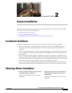
Chapter 2 Camera Installation
Installing the IP Camera with a Vandal Resistant Enclosure
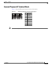
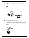
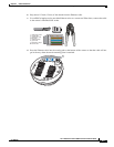
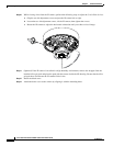
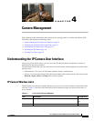
h. Connect the power and I/O cables to the GPIO terminal block
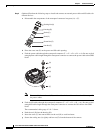
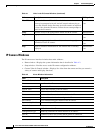
Step 7 Use the included L-type wrench to secure the conduit base to the mounting plate with the three included
screws.
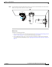
Step 8 Remove the black cover.
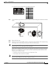
Step 9 (Optional) Use mini cable with BNC connector to temporarily attach an NTSC or PAL compliant analog
video display device to the analog video out port on the rear of the IP camera.
Note The mini cable with BNC adapter is included in the audio/video cables accessory kit, which you can
purchase from Cisco (Cisco part number CIVS-AVCABLE).
Analog video is enabled by default to allow you to adjust the camera field of view during installation.
However, it is not supported as a normal camera feed and is automatically disabled when any of the
following camera settings are made:
• The primary video stream frame rate must be set higher than 15 fps.
• The secondary video stream must is enabled.
Note We recommend that you disable analog video after installation. To disable analog video, see the Cisco
Video Surveillance 6000 Series IP Camera Configuration Guide.
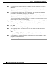
Pin Description
1 12 VDC-
2 12 VDC+
3 24 VAC
4 24 VAC
5 DI-
6 DI+
7 DO-
8 DO+
87654321